
CONVENTIONAL BRAKE SYSTEM
P-19parts diagramMaster cylinder procedure specific to K8 DOHC (1.8L V6). Hose item (3) is MTX (manual transaxle) only.
MASTER CYLINDER (K8 DOHC)
Removal / Installation / Inspection
Removal / Installation / Inspection (K8 DOHC)
- 1Remove in the order shown in the figure, referring to Removal Note.
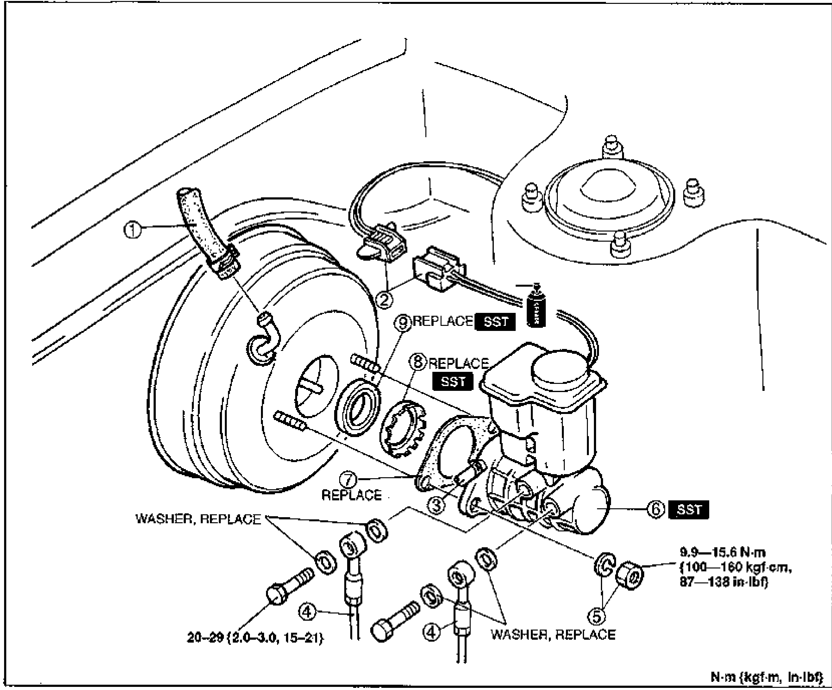
- 2Install in the reverse order of removal, referring to Installation Note.
- 3After installation, add brake fluid, bleed air, and check for fluid leakage.
CAUTION
Before removing the master cylinder, be sure to disconnect the vacuum hose (with check valve) from the power brake unit. Removing the master cylinder with vacuum remaining in the power brake unit will cause the master cylinder piston to pop out and drain the brake fluid.
Parts DiagramFig. fig1