Assembly
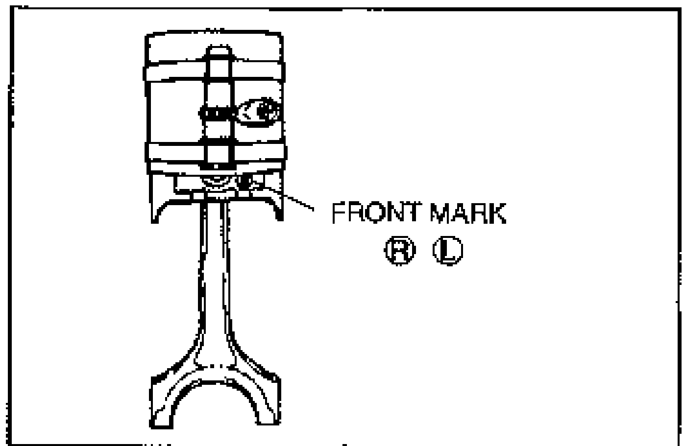
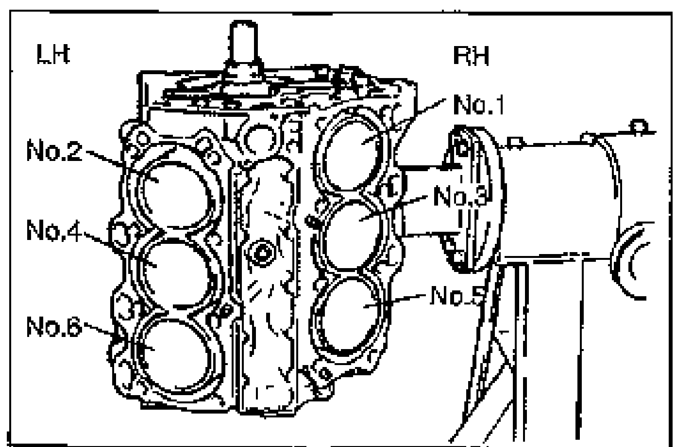
B2-93prose procedureV6 cylinder bank numbering: LH bank = No.2/4/6, RH bank = No.1/3/5. Pistons marked L for left bank, R for right bank.
Crankshaft / rear oil seal
- 3Measure the crankshaft end play.
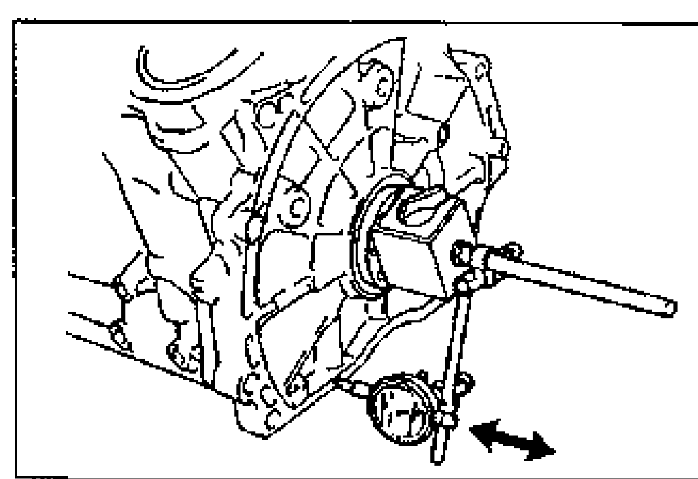
- 4If the end play exceeds the maximum, grind the crankshaft and install oversize thrust bearings or replace the crankshaft and thrust bearing.
- 5Apply a small amount of clean engine oil to the lip of a new rear oil seal.
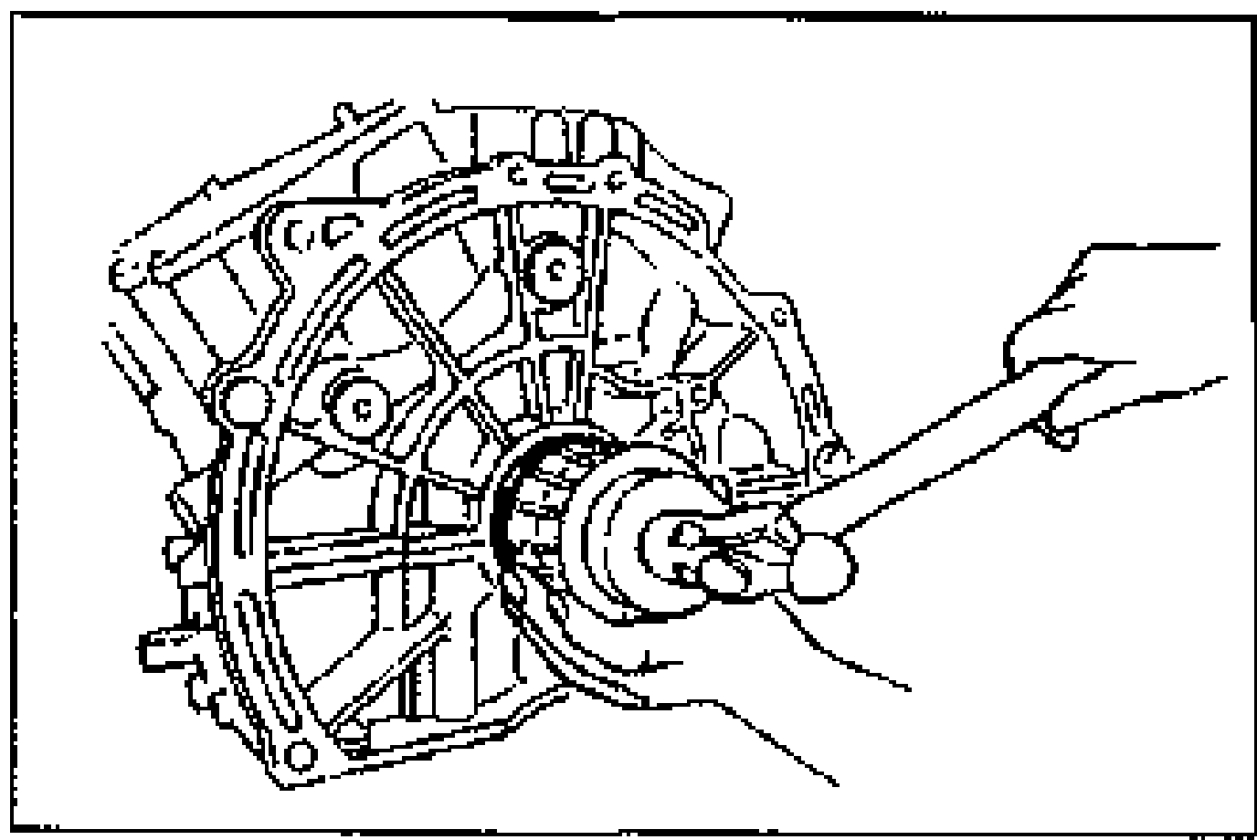
- 6Push the rear oil seal slightly in by hand.
- 7Tap the oil seal in evenly by using the SST and a hammer.Oil seal outer diameter: 93mm {3.66 in}Oil seal inner diameter: 75mm {2.87 in}
| Specification | Value |
|---|---|
| End playcrankshaft | 0.080-0.282mm {0.0032-0.0111 in} |
| Maximumcrankshaft end play | 0.32mm {0.013 in} |
| Thrust bearing width Standard | 2.000-2.050mm {0.0788-0.0807 in} |
| Thrust bearing width 0.25mm {0.01 in} oversize | 2.175mm {0.0837-0.0856 in} |
| Thrust bearing width 0.50mm {0.02 in} oversize | 2.250-2.300mm {0.0886-0.0905 in} |
| Protrusionrear oil seal | 0-0.7mm {0-0.021 in} |
End playcrankshaft
0.080-0.282mm {0.0032-0.0111 in}
Maximumcrankshaft end play
0.32mm {0.013 in}
Thrust bearing width Standard
2.000-2.050mm {0.0788-0.0807 in}
Thrust bearing width 0.25mm {0.01 in} oversize
2.175mm {0.0837-0.0856 in}
Thrust bearing width 0.50mm {0.02 in} oversize
2.250-2.300mm {0.0886-0.0905 in}
Protrusionrear oil seal
0-0.7mm {0-0.021 in}
Piston and Connecting Rod Assembly
- 1Rotate the engine as shown.Assembly is easier if the pistons are installed with the crankpin at the BDC position.
- 2Remove any foreign material and oil from the connecting rod journals and bearings.
- 3Install the upper connecting rod bearings in the connecting rods.
- 4Apply a liberal amount of clean engine oil to the cylinder walls, pistons, piston rings and connecting rod cap bolts.
- 5Check the piston rings for proper end gap positioning.
- 6Insert the piston and connecting rod assembly into the cylinder block with the L mark (left bank) and the R mark (right bank) facing the front of the engine. Use a piston installer tool to install.