
ON-VEHICLE MAINTENANCE — HLA Removal/Installation Note (Harness and hoses)
B2-38prose procedureThrottle cable adjustment applies to ATX; V6 (K8-ZE) harness layout.
HLA component reference index
1
ComponentAccelerator cable
NoteInstallation Note
Referencepage B2-36
2
ComponentThrottle cable (ATX)
NoteAdjustment
Referencesection K
3
ComponentHigh-tension leads
Note
Reference
4
ComponentHarness and hoses
NoteRemoval / Installation Note
Referencebelow
5
ComponentIntake manifold assembly
NoteRemoval Note
Referencepage B2-26
5
ComponentIntake manifold assembly
NoteInstallation Note
Referencepage B2-34
6
ComponentCylinder head cover
NoteRemoval Note
Referencepage B2-26
6
ComponentCylinder head cover
NoteInstallation Note
Referencepage B2-33
7
ComponentDistributor
NoteInstallation Note
Referencepage B2-33
8
ComponentCamshaft pulley
NoteRemoval Note
Referencepage B2-27
8
ComponentCamshaft pulley
NoteInstallation Note
Referencepage B2-32
9
ComponentCamshaft cap and oil seal
NoteRemoval Note
Referencepage B2-27
9
ComponentCamshaft cap and oil seal
NoteInstallation Note
Referencepage B2-30
10
ComponentCamshaft
NoteInstallation Note
Referencepage B2-30
11
ComponentHLA
NoteInspection
Referencepage B2-80
Removal / Installation Note
Harness and hoses
- 1Disconnect the harness connectors and hoses shown.
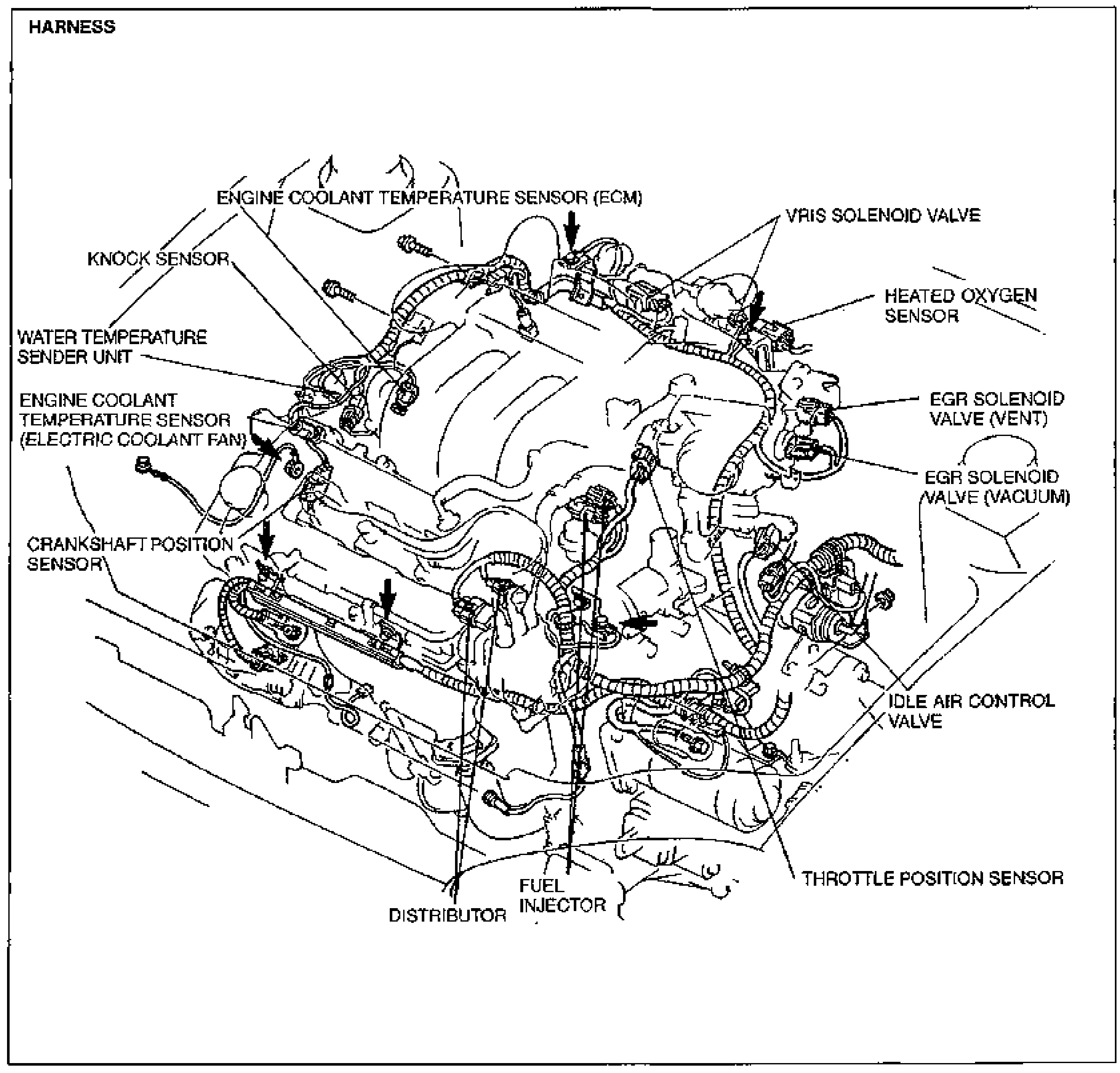
- 2Connect the harness connectors and hoses in the reverse order of disconnection.