
Inspection / Repair - Camshaft (oil clearance / cap installation)
B2-79prose procedureSeparate RH and LH cylinder-head bolt orders and thrust-cap marks (RH = "4", LH = "A"); V6 K8-ZE dual-bank DOHC. Distributor cap appears on the LH head.
Camshaft journal oil clearance (continued)
- 3Position Plastigage atop each journal in the journal axial direction.
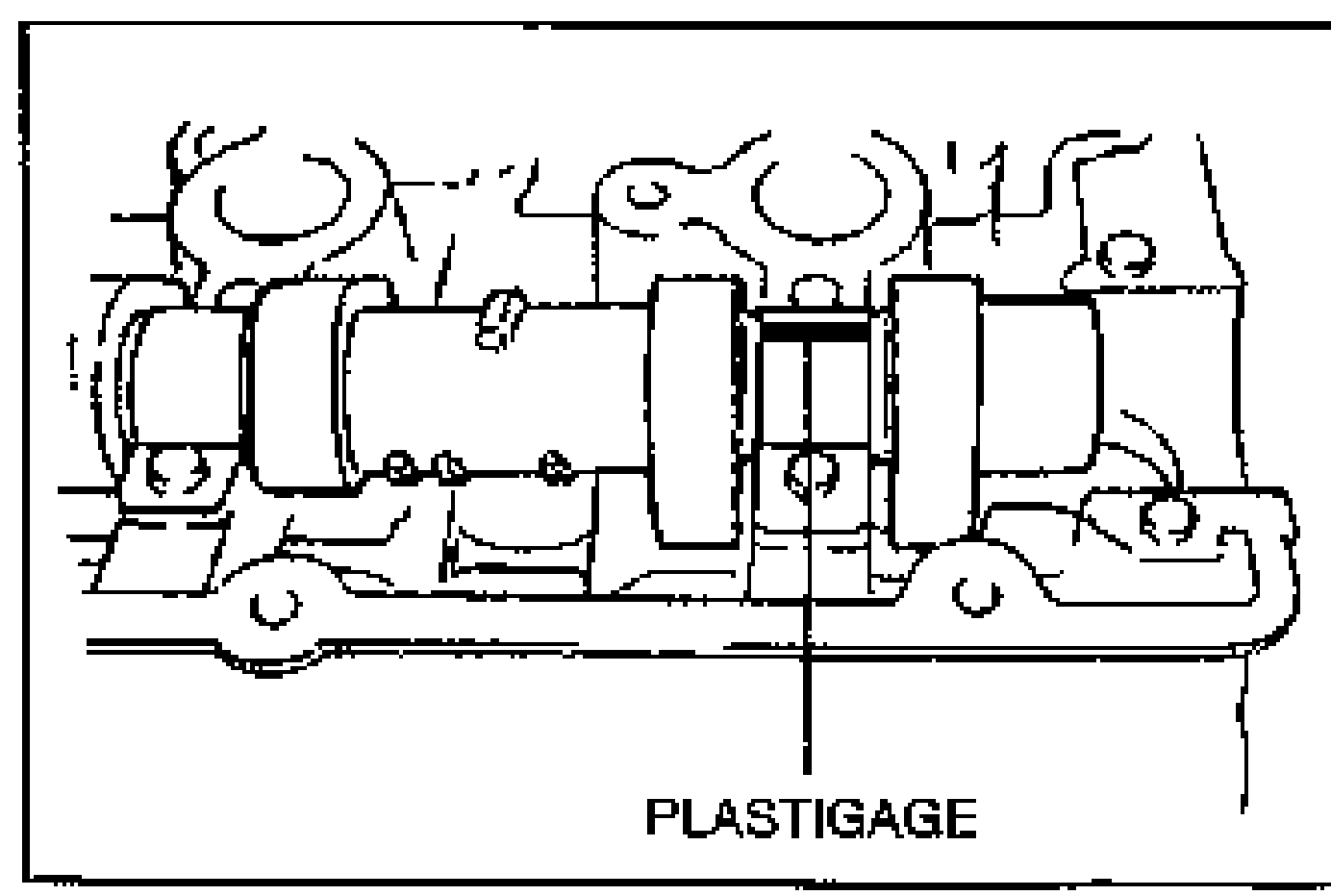
- 4Do not rotate the camshaft when measuring the oil clearances.
- 5Install the thrust caps onto the cylinder heads. Hand tighten the bolts in five or six steps in the order shown, until the thrust caps fully seated on the cylinder heads.Install the thrust caps (RH is ⌄4⌅ mark, LH is ⌄A⌅ mark) first. Otherwise, camshaft can be broken or damaged.
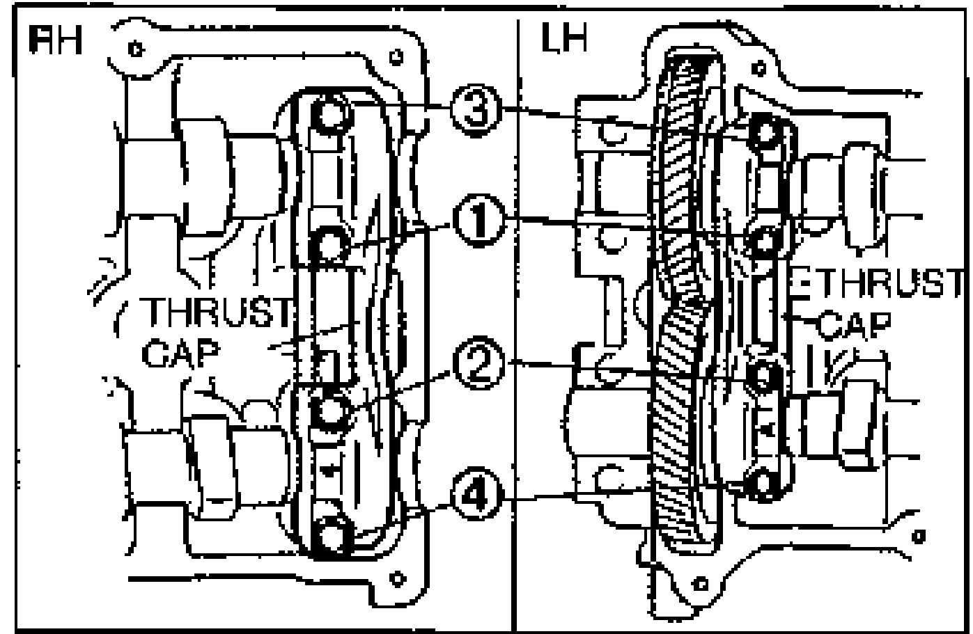
- 6Install the camshaft caps onto the cylinder heads. Hand tighten the bolts in five or six steps in the order shown, until the camshaft caps fully seated in the cylinder heads.
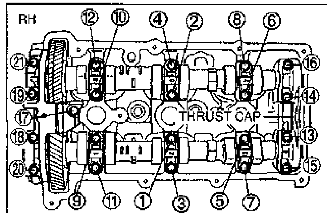
- 7Tighten the bolts in the order shown.
- 8Retighten the bolts in the order shown.
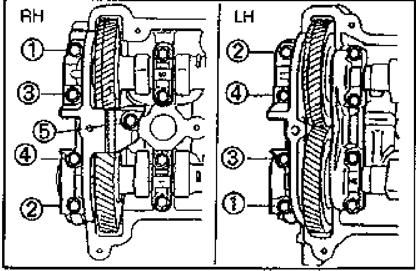
- 9Loosen the camshaft cap bolts in five or six steps in the order shown.Remove the thrust cap only after removing all camshaft caps. Otherwise, the thrust cap can be damaged.
CAUTION
Install the thrust caps (RH is ⌄4⌅ mark, LH is ⌄A⌅ mark) first. Otherwise, camshaft can be broken or damaged.
| Specification | Value |
|---|---|
| Tightening torque (step 7) | 11.3 - 14.2N·m |
| Tightening torque (step 8 retighten) | 11.3 - 14.2N·m |
Tightening torque (step 7)
11.3 - 14.2N·m
Tightening torque (step 8 retighten)
11.3 - 14.2N·m
CAUTION
Remove the thrust cap only after removing all camshaft caps. Otherwise, the thrust cap can be damaged.