
REMOVAL
B2-44parts diagramOil cooler hose (9) and control cable (16) apply to ATX. A/C compressor (15) only if equipped.
WARNING
Fuel line spills and leaks are dangerous. Fuel can ignite and cause serious injuries or death and damage. Fuel can also irritate skin and eyes. To prevent this, always complete the "Fuel Line Safety Procedures" on section F2.
PROCEDURE
Removal Procedure
- 1Disconnect the negative battery cable.
- 2Drain the engine coolant and transaxle oil.
- 3Remove the hood and front wheels.
- 4Remove in the order shown in the figure, referring to Removal Note.
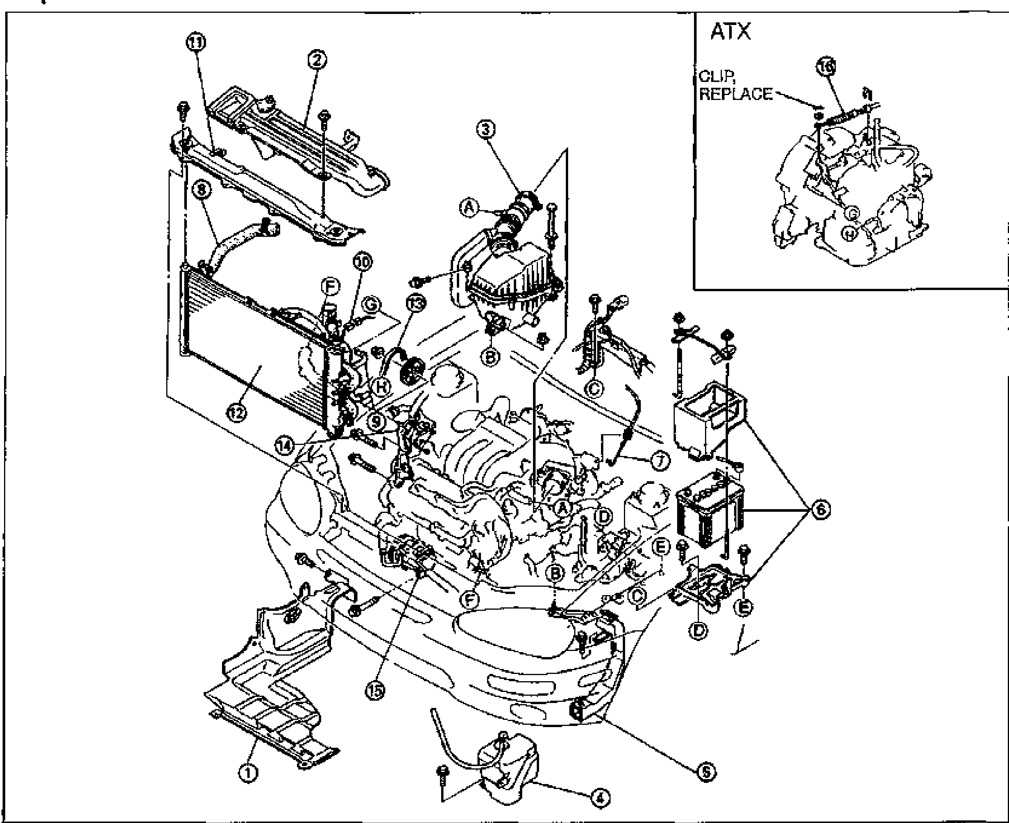
Step 1
Step 1 — removal order
1
PartSplash shield
Reference—
2
PartFresh-air duct
Reference—
3
PartAir cleaner assembly
Reference—
4
PartCoolant reservoir
Reference—
5
PartBattery duct
Reference—
6
PartBattery and carrier
Reference—
7
PartAccelerator cable
Reference—
8
PartRadiator hose
Reference—
9
PartOil cooler hose (ATX)
Reference—
10
PartCoolant fan motor connector
Reference—
11
PartShroud upper panel
Reference—
12
PartRadiator and coolant fan assembly
Reference—
13
PartDrive belt
ReferenceRemoval — page B2-7
14
PartP/S oil pump
ReferenceRemoval Note — page B2-45
15
PartA/C compressor (if equipped)
ReferenceRemoval Note — page B2-46
16
PartControl cable (ATX)
Reference—