
Inspection / Repair - Cylinder Head / Valve Mechanism
B2-74spec tableCylinder head (continued)
- 3Inspect for the following and repair or replace the cylinder head if necessary: (1) Sunken valve seats; (2) Damaged intake and exhaust manifold contact surfaces; (3) Excessive camshaft oil clearances and end play.
- 4If the cylinder head distortion exceeds the specification, replace the cylinder head or grind the cylinder head surface.
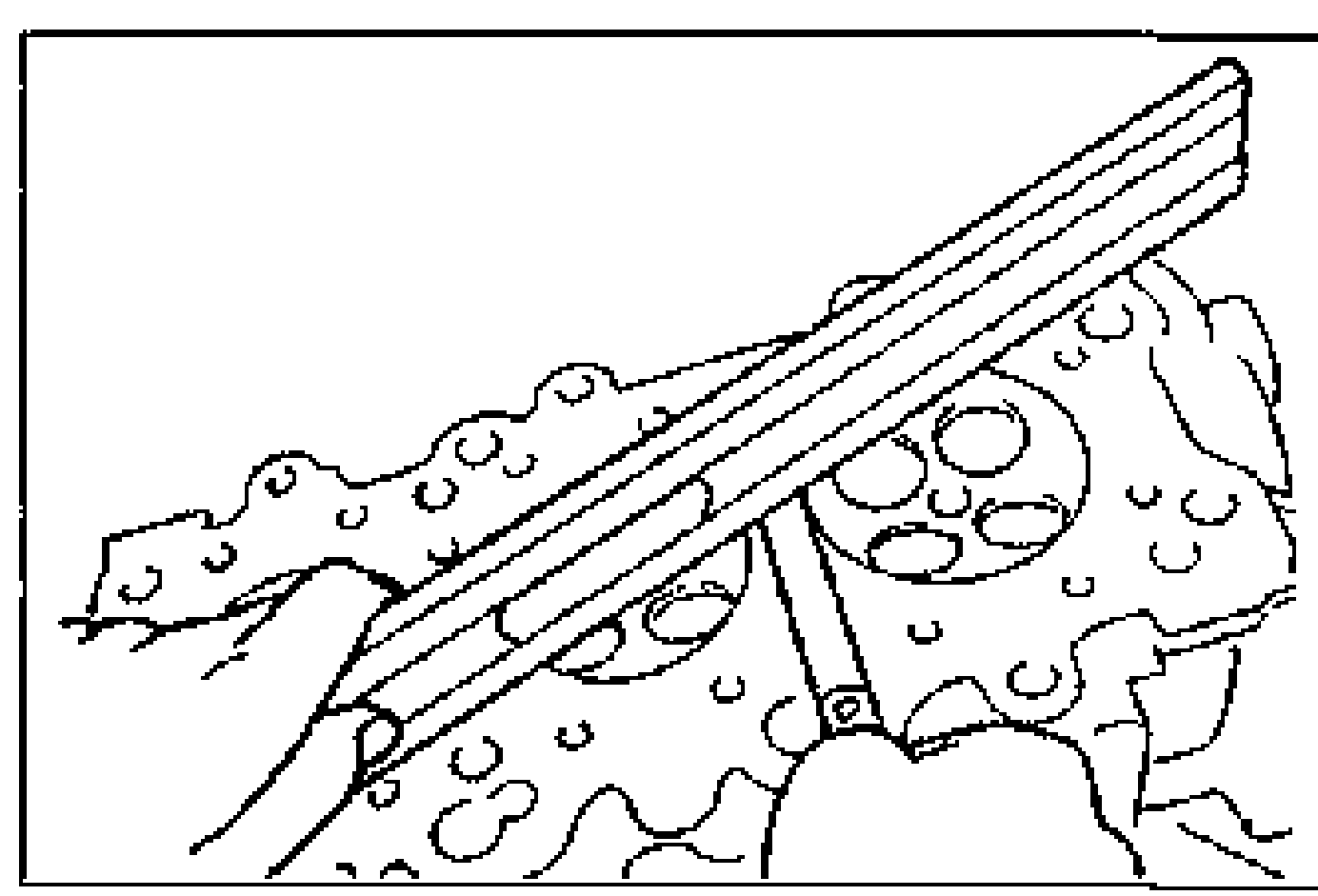
- 5If the cylinder head height is not within the specification, replace it.
- 6Measure the intake and exhaust manifold contact surfaces for distortion in the six directions as shown.
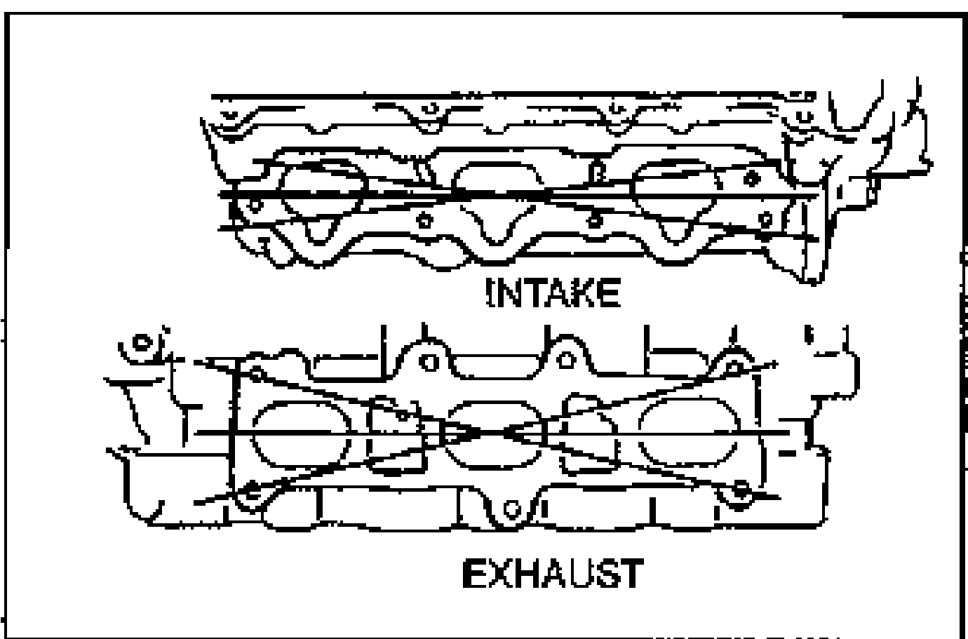
- 7If distortion exceeds the specification, grind the surface or replace the cylinder head.
| Specification | Value |
|---|---|
| Grindingmax. | 0.15 {0.006}mm {in} |
| Height | 133.4-133.6 {5.252-5.259}mm {in} |
| Distortion (manifold contact surfaces)max. | 0.10 {0.004}mm {in} |
Grindingmax.
0.15 {0.006}mm {in}
Height
133.4-133.6 {5.252-5.259}mm {in}
Distortion (manifold contact surfaces)max.
0.10 {0.004}mm {in}
VALVE MECHANISM
Valve and Valve Guide
- 1Inspect each valve for the following. Replace or resurface the valve as necessary: (1) Damaged or bent stem; (2) Rough or damaged face; (3) Damaged or unevenly worn stem tip.
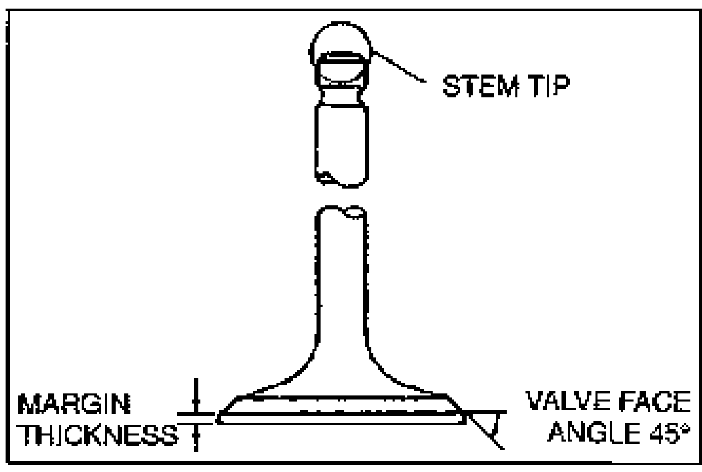
- 2Measure the valve head margin thickness. Replace the valve if necessary.
- 3Measure the valve length. Replace the valve if necessary.
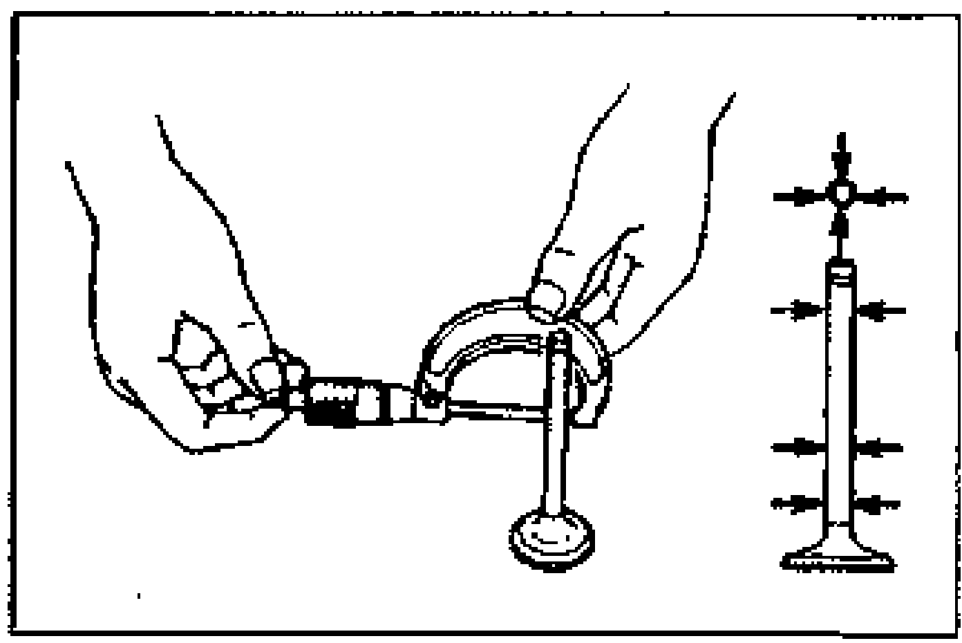
- 4Measure the valve stem diameter. Replace the valve if necessary.
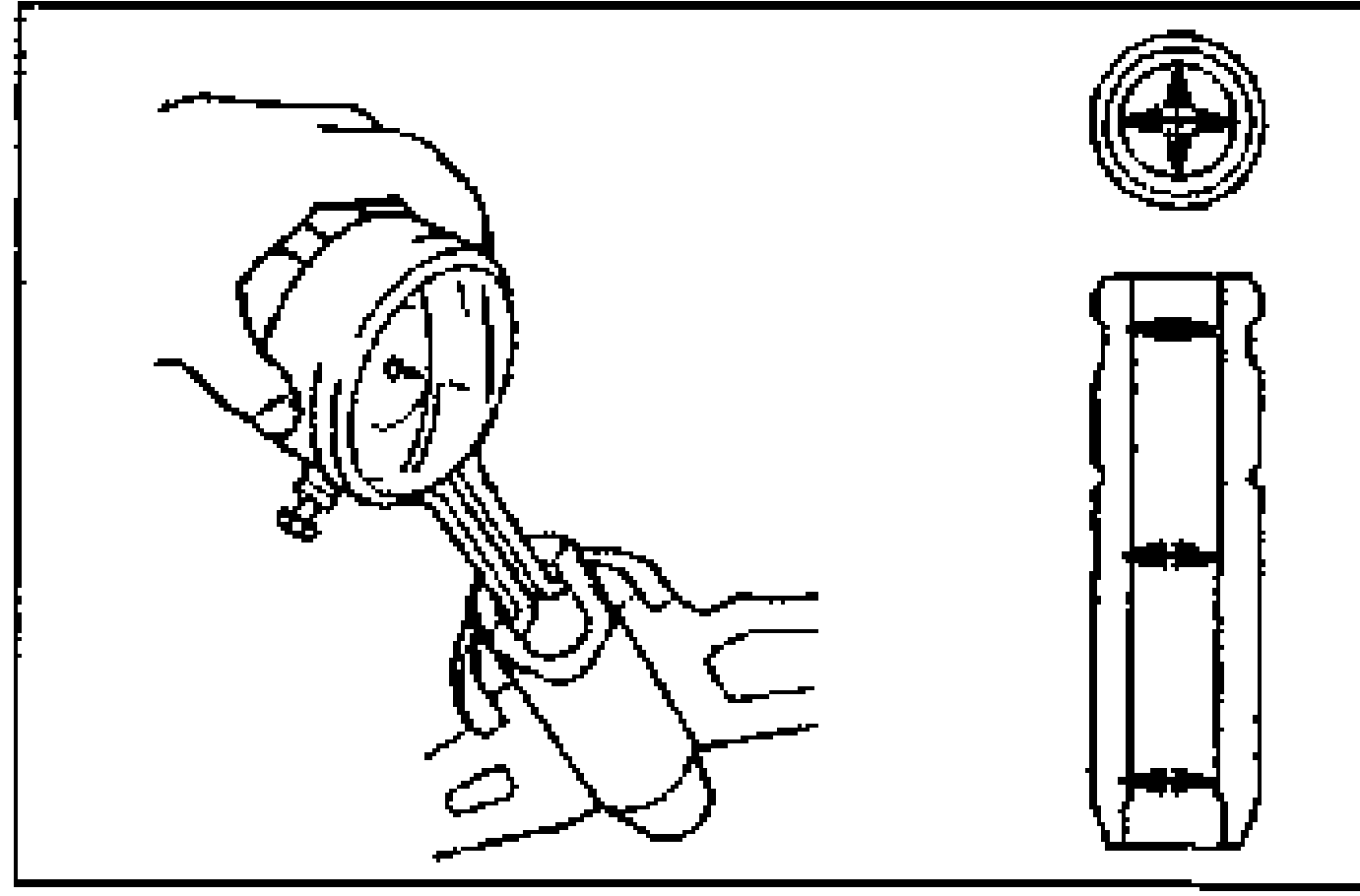
- 5Measure the valve guide inner diameter. Replace the guide if necessary.
| Specification | Value |
|---|---|
| Margin thicknessIN: min. | 0.9 {0.035}mm {in} |
| Margin thicknessEX: min. | 1.0 {0.039}mm {in} |
| LengthStandard IN | 94.11 {3.7051}mm {in} |
| LengthStandard EX | 95.19 {3.7476}mm {in} |
| LengthMinimum IN | 93.61 {3.6854}mm {in} |
| LengthMinimum EX | 94.69 {3.7279}mm {in} |
| DiameterStandard IN | 5.970-5.985 {0.2351-0.2356}mm {in} |
| DiameterStandard EX | 5.965-5.980 {0.2349-0.2354}mm {in} |
| DiameterMinimum IN | 5.920 {0.2331}mm {in} |
| DiameterMinimum EX | 5.915 {0.2329}mm {in} |
| Inner diameterIN | 6.01-6.03 {0.2367-0.2374}mm {in} |
| Inner diameterEX | 6.01-6.03 {0.2367-0.2374}mm {in} |
Margin thicknessIN: min.
0.9 {0.035}mm {in}
Margin thicknessEX: min.
1.0 {0.039}mm {in}
LengthStandard IN
94.11 {3.7051}mm {in}
LengthStandard EX
95.19 {3.7476}mm {in}
LengthMinimum IN
93.61 {3.6854}mm {in}
LengthMinimum EX
94.69 {3.7279}mm {in}
DiameterStandard IN
5.970-5.985 {0.2351-0.2356}mm {in}
DiameterStandard EX
5.965-5.980 {0.2349-0.2354}mm {in}
DiameterMinimum IN
5.920 {0.2331}mm {in}
DiameterMinimum EX
5.915 {0.2329}mm {in}
Inner diameterIN
6.01-6.03 {0.2367-0.2374}mm {in}
Inner diameterEX
6.01-6.03 {0.2367-0.2374}mm {in}