
Assembly
B2-90prose procedurePiston rings (continued)
- 2Verify that the spacer tang separates the rails, and that the rails turn smoothly in both directions.
- 3Install the rings with the R marks upward.
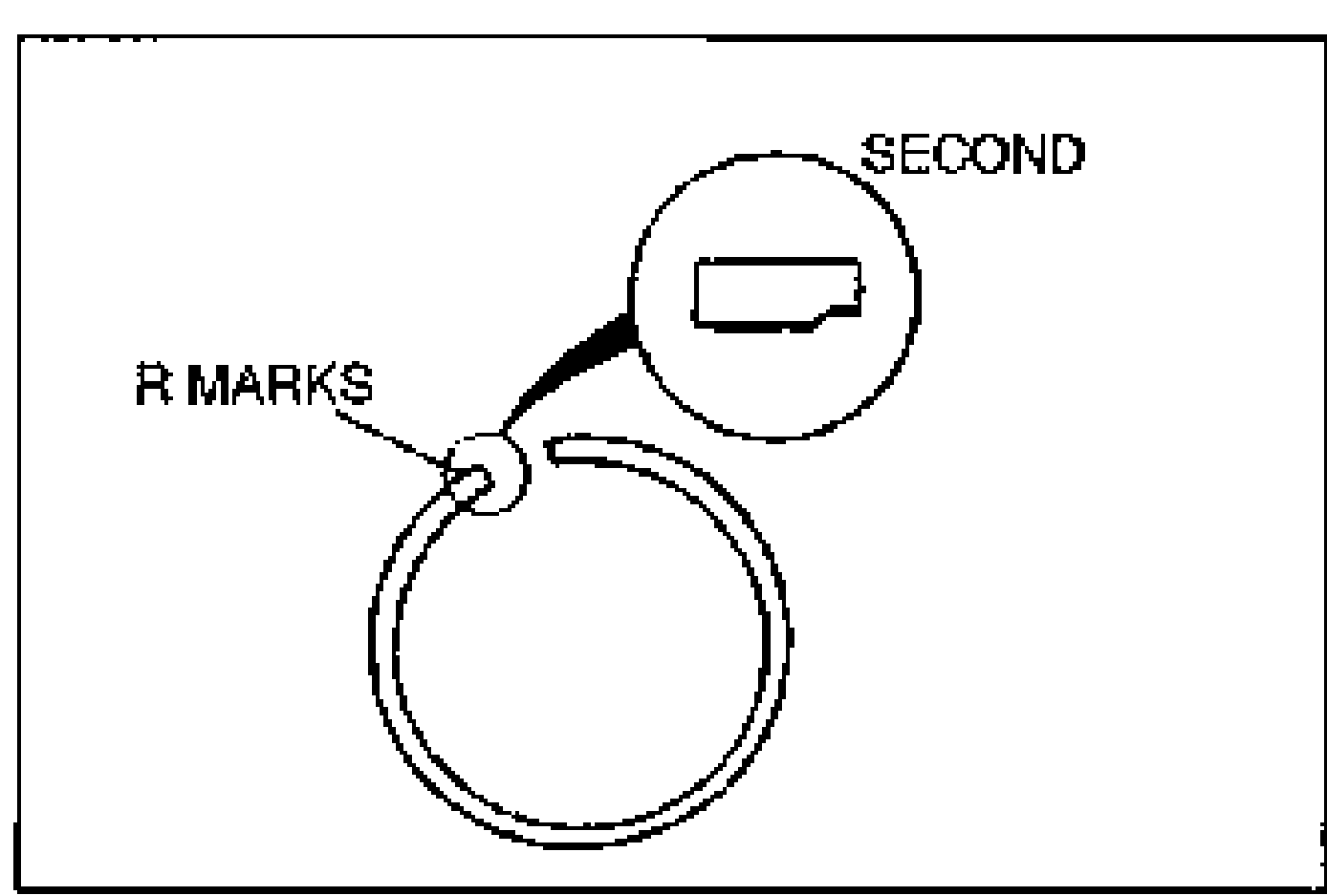
- 4Using a piston ring expander, install the second ring with the scraper face downward.
- 5Using a piston ring expander, install the top ring.
- 6Apply a liberal amount of clean engine oil to the piston rings.
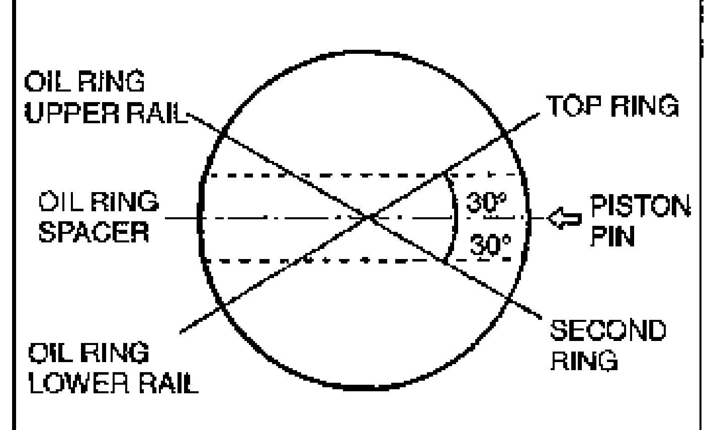
- 7Position the end gap of each ring as shown.
Oil jet
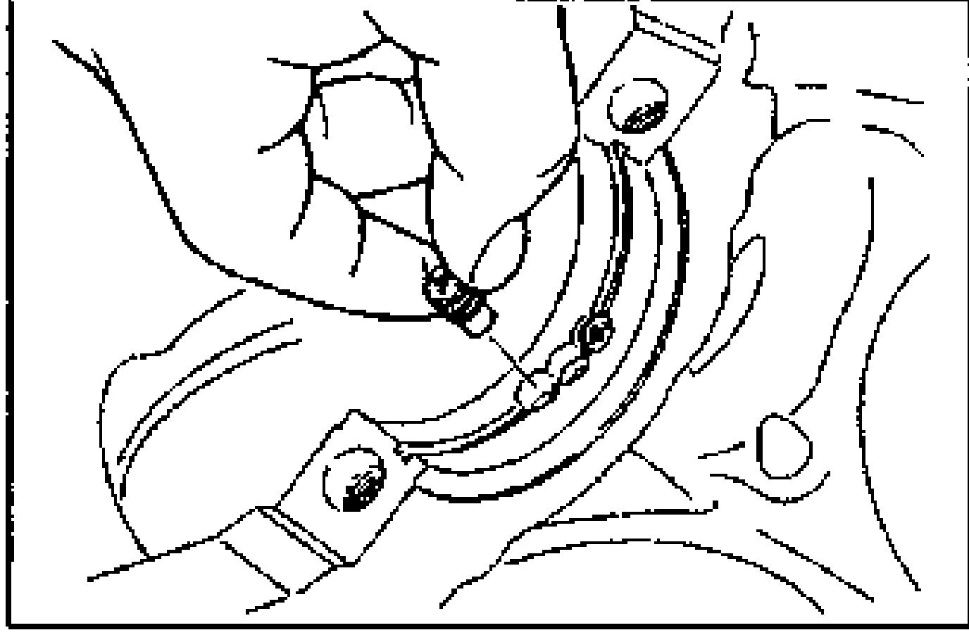
- 1Apply thread locking compound to the oil jet threads.
- 2Install the oil jets into the upper cylinder block.
| Specification | Value |
|---|---|
| Oil jet | 3.0 - 4.9N·m |
Oil jet
3.0 - 4.9N·m
Crankshaft
- 1Measure the main bearing oil clearances as described below.
Oil clearance inspection
- 1Remove any foreign material and oil from the journals and bearings.
- 2Install the upper main bearings (with oil groove) and the upper thrust bearings.No.4 bearing is wider than other bearings.
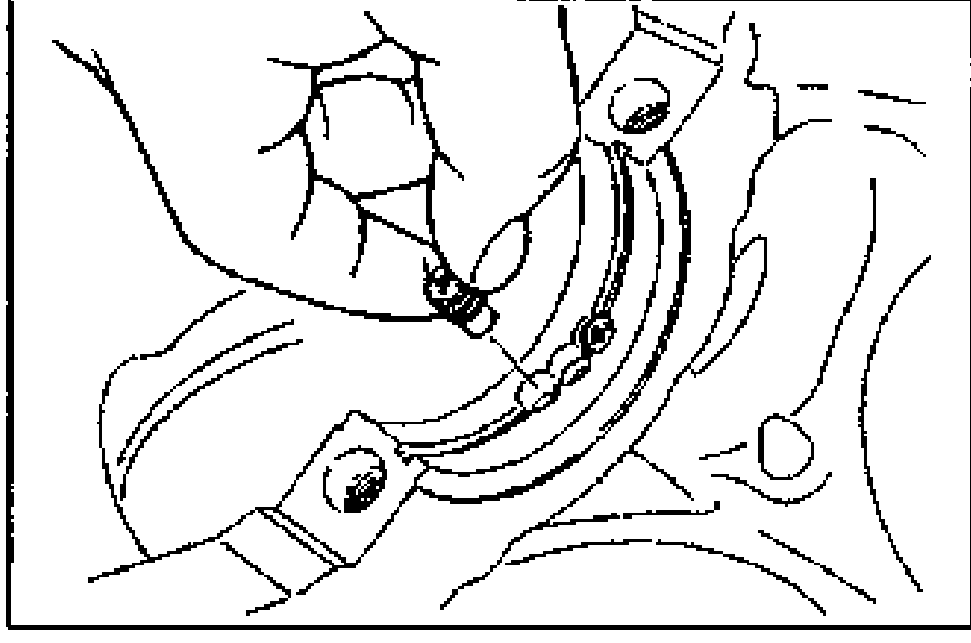
- 3Install the lower cylinder block along with the lower main bearings and thrust bearings.
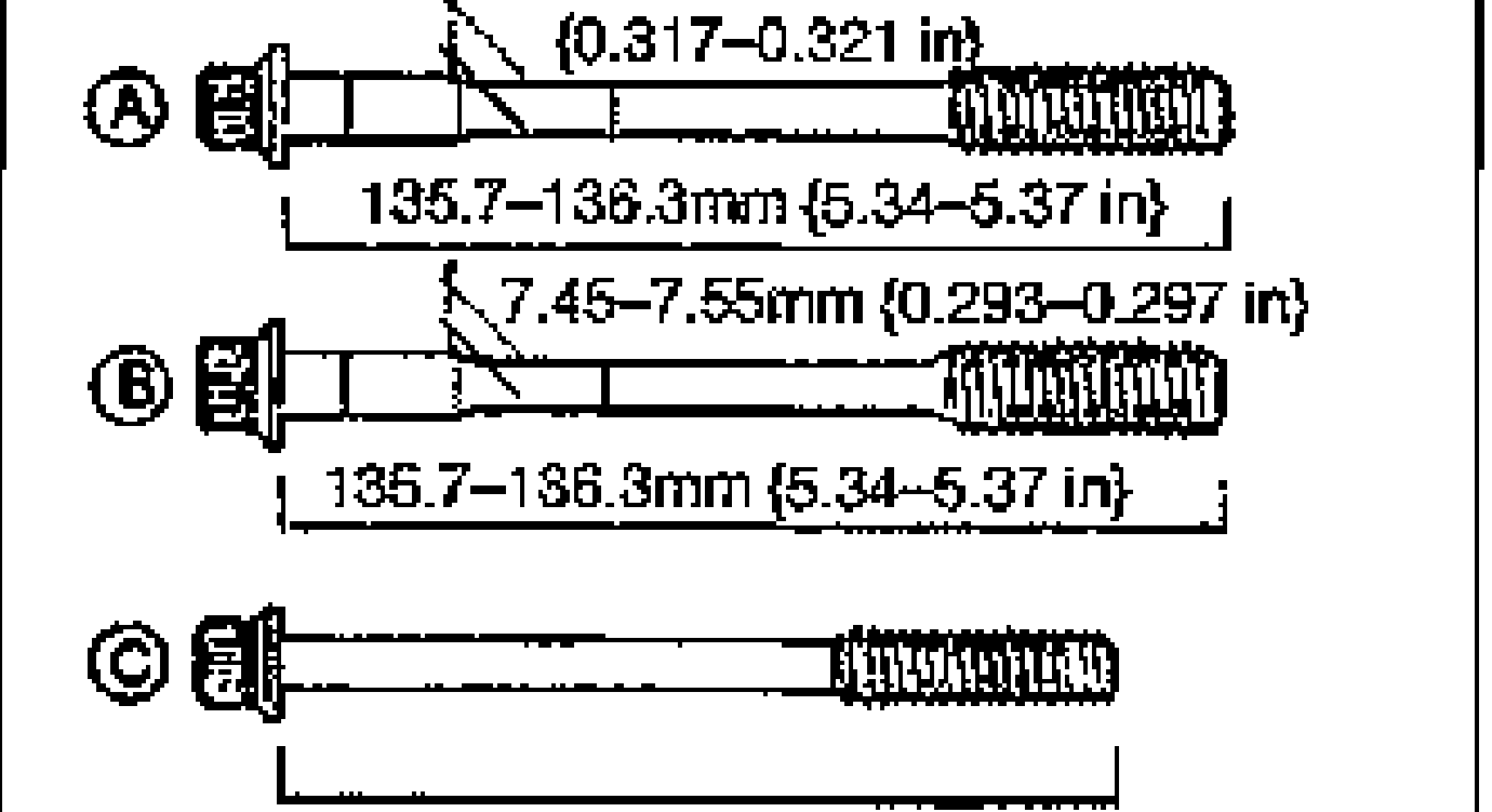
- 4Measure the length of lower cylinder block bolt. Replace it if the length exceeds the maximum.
| Specification | Value |
|---|---|
| Bolt A and B Length | 135.7-136.3mm {5.343-5.361 in} |
| Bolt A and B Maximum | 138.5mm {5.453 in} |
| Bolt C Length | 119.7-120.3mm {4.713-4.736 in} |
| Bolt C Maximum | 121.0mm {4.764 in} |
Bolt A and B Length
135.7-136.3mm {5.343-5.361 in}
Bolt A and B Maximum
138.5mm {5.453 in}
Bolt C Length
119.7-120.3mm {4.713-4.736 in}
Bolt C Maximum
121.0mm {4.764 in}