ASSEMBLY
B2-89prose procedurePiston pin pressing
- 3Set the SST (stopper bolt) so that the depth L is as specified.
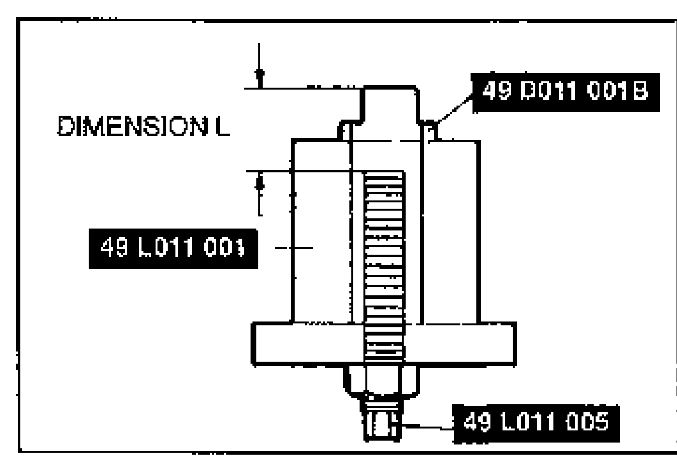
- 4Tighten the locknut.
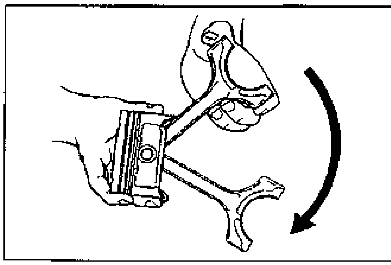
- 5Assemble the piston and the connecting rod.
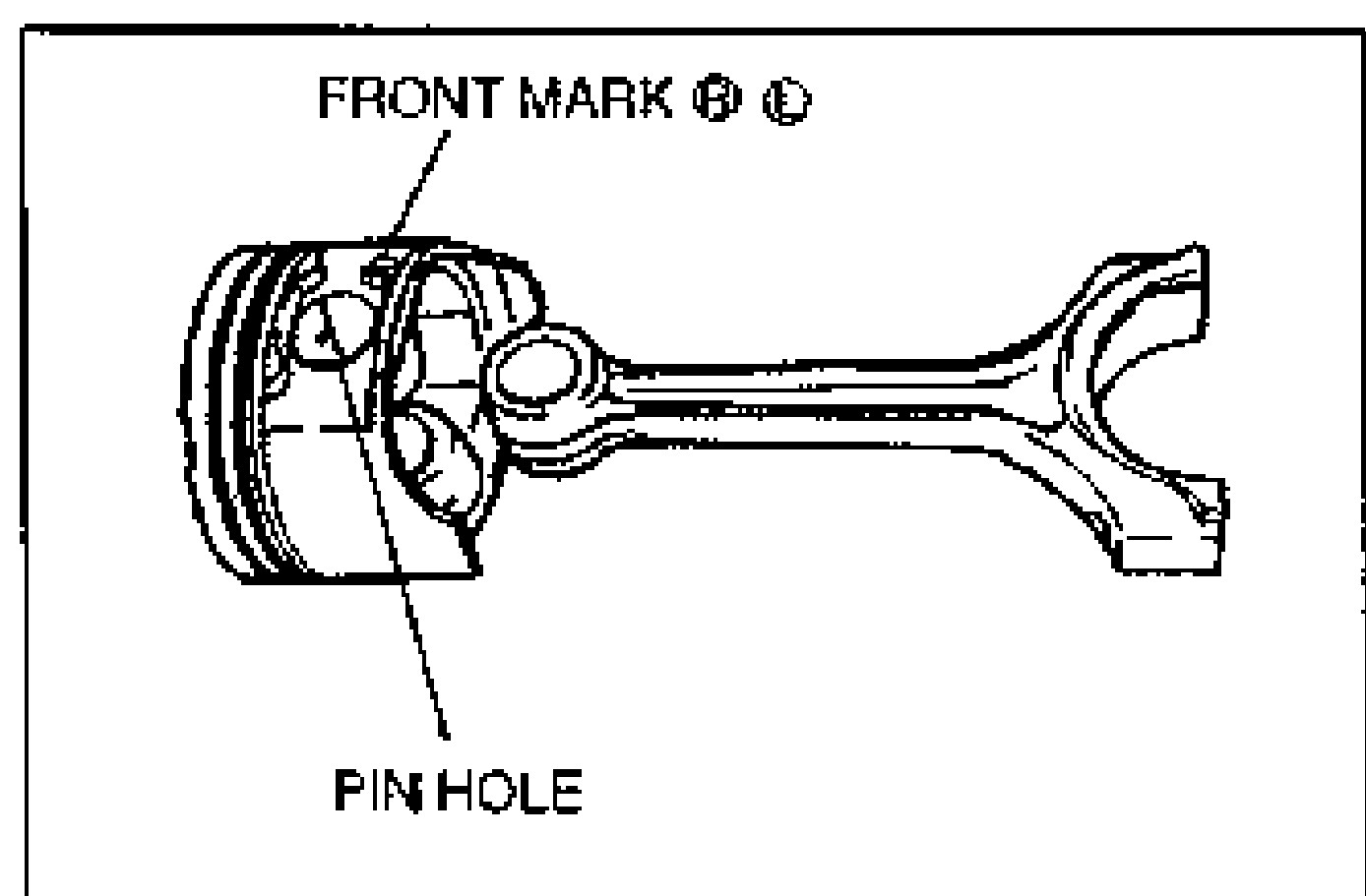
- 6Insert the SSTs (tool set, piston pin setting) assembled in step 1 into the piston pin hole.
- 7Mount the piston and connecting rod onto the SST (Support block).
- 8Verify that the SSTs fits squarely into the piston before pressing.
- 9Press the piston pin into the piston and connecting rod until the SST (piston pin guide) contacts the stopper bolt.
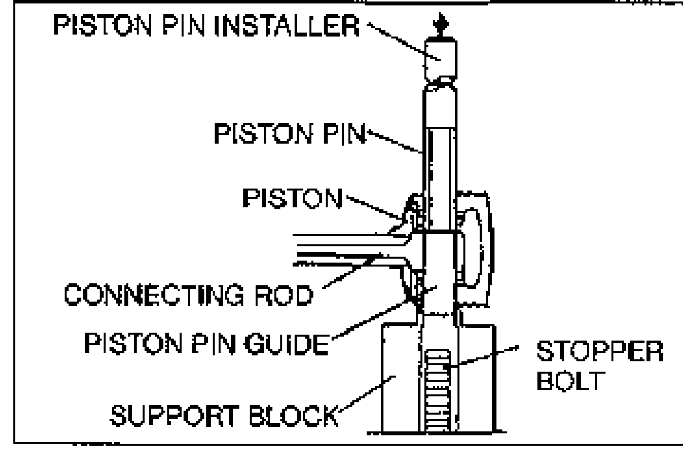
- 10While inserting the piston pin, check the pressing force. If it is less than specified, replace the piston pin and/or the connecting rod.
- 11Check the connecting rod oscillation torque. (Refer to page B2-69.)
| Specification | Value |
|---|---|
| Depth L | 61.4 mm {2.42 in} |
| Pressing force | 3,924–12,753 N {400–1,300 kgf, 880–2,860 lbf} |
Depth L
61.4 mm {2.42 in}
Pressing force
3,924–12,753 N {400–1,300 kgf, 880–2,860 lbf}
Piston Ring
CAUTION
If reusing an oil ring, it must be reinstalled in the same place and face the same direction as when removed. If this is not done, it can cause premature and uneven wear.
NOTE
The upper and lower rails are the same. They can be installed with either face upward.
Piston ring installation
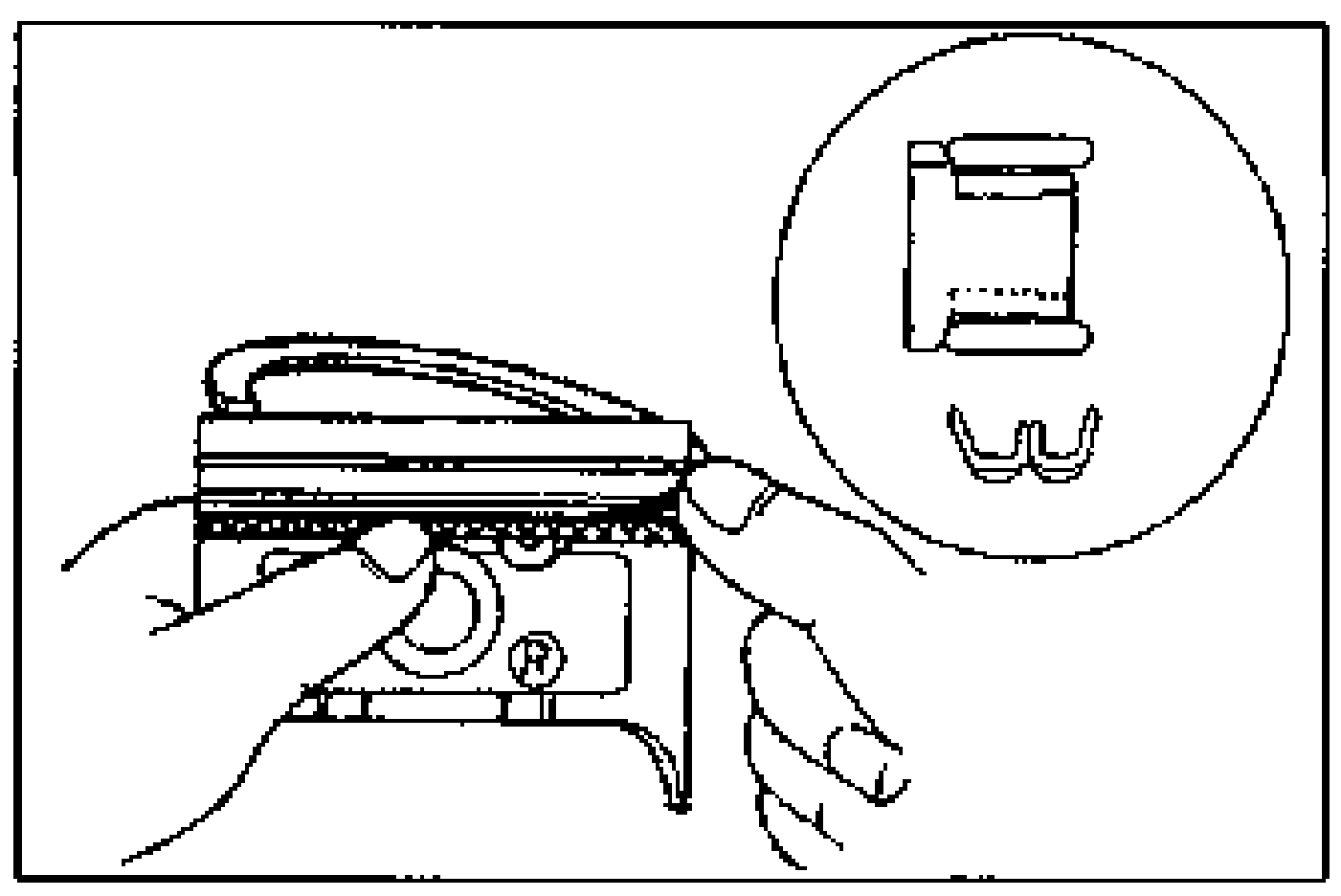
- 1Install the three-piece oil rings on the pistons. (1) Apply clean engine oil to the oil ring spacer and rails. (2) Install the oil ring spacer so that the opening faces upward. (3) Install the upper rail and lower rail.