
Inspection / Repair - Valve Guide
B2-75prose procedureValve and Valve Guide (continued)
- 6Calculate the valve stem-to-guide clearance. Subtract the outer diameter of the valve stem from the inner diameter of the corresponding valve guide.
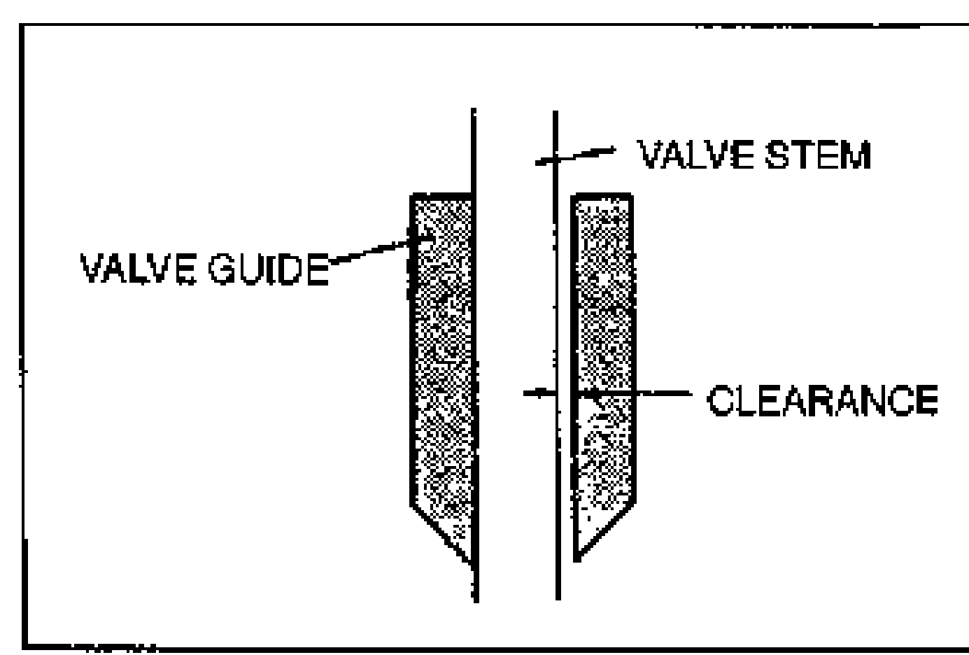
- 7If the clearance exceeds the maximum, replace the valve and/or valve guide.
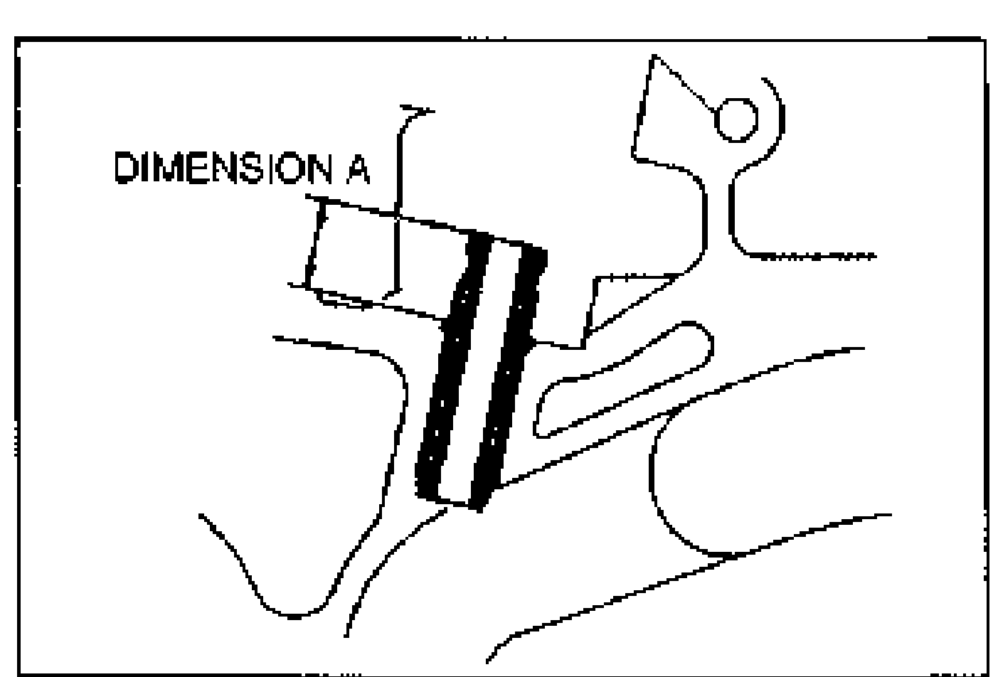
- 8Measure the valve guide projection height (dimension A). Replace the guide if necessary.
| Specification | Value |
|---|---|
| ClearanceIN | 0.025-0.060 {0.0010-0.0023}mm {in} |
| ClearanceEX | 0.030-0.065 {0.0012-0.0025}mm {in} |
| ClearanceMaximum | 0.20 {0.008}mm {in} |
| Height AIN | 14.7-15.3 {0.579-0.602}mm {in} |
| Height AEX | 12.2-12.8 {0.481-0.503}mm {in} |
ClearanceIN
0.025-0.060 {0.0010-0.0023}mm {in}
ClearanceEX
0.030-0.065 {0.0012-0.0025}mm {in}
ClearanceMaximum
0.20 {0.008}mm {in}
Height AIN
14.7-15.3 {0.579-0.602}mm {in}
Height AEX
12.2-12.8 {0.481-0.503}mm {in}
Replacement of valve guide
NOTE
The intake and exhaust valve guides are the same.
Replacement of valve guide
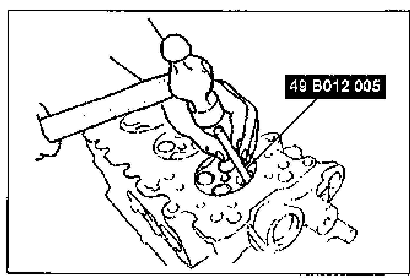
- 1Remove the valve guide from the combustion chamber side by using the SST.
- 2Assemble the SST so that depth L is as specified.
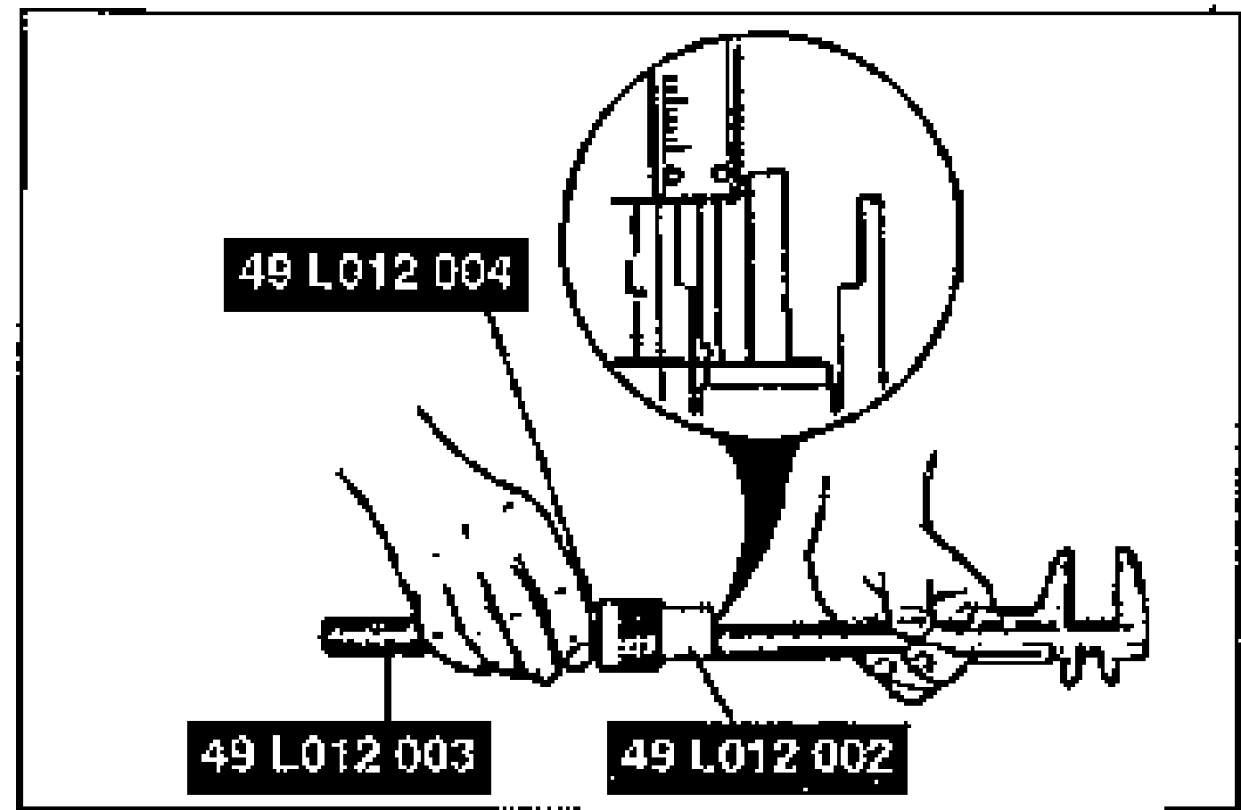
- 3Tighten the nut.
| Specification | Value |
|---|---|
| Depth LIN | 14.7-15.3 {0.579-0.602}mm {in} |
| Depth LEX | 12.2-12.8 {0.481-0.503}mm {in} |
Depth LIN
14.7-15.3 {0.579-0.602}mm {in}
Depth LEX
12.2-12.8 {0.481-0.503}mm {in}