
ON-VEHICLE MAINTENANCE — Installation Note
B2-29prose procedureCylinder head gaskets are bank-specific: gasket marked L on the left bank, marked R on the right bank (V6).
Installation Note
Cylinder head
- 1Measure the amount of oil control plug projection from the deck of the cylinder block.Projection: 8.0-9.0 mm {0.315-0.354 in}
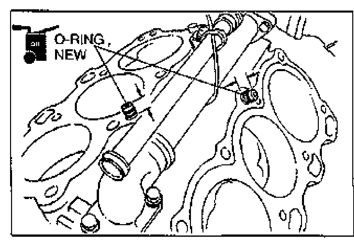
- 2Apply clean engine oil to new O-rings and install them to the oil control plugs.
- 3Thoroughly remove all dirt, oil, and other material from the decks of the cylinder block.
- 4Turn the crankshaft clockwise and apply engine oil to the cylinder walls.
- 5Place a new cylinder head gasket (marked L) on the left bank.
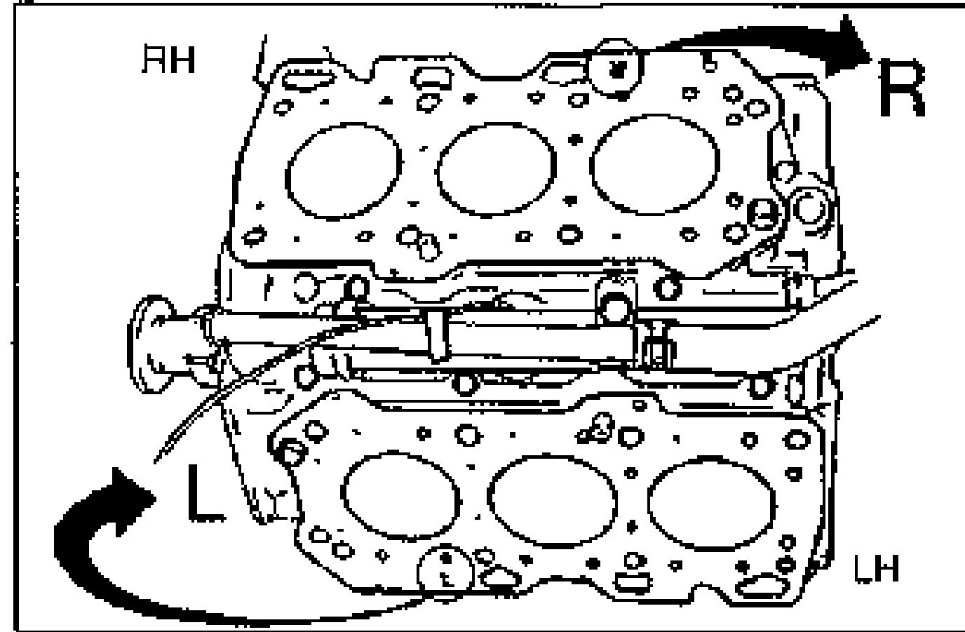
- 6Place a new cylinder head gasket (marked R) on the right bank.
- 7Install the cylinder heads to the cylinder block.
- 8Tighten the cylinder head bolts as described below.
- 1Before installation, measure the length of each bolt. Replace the bolt if it exceeds the maximum length.
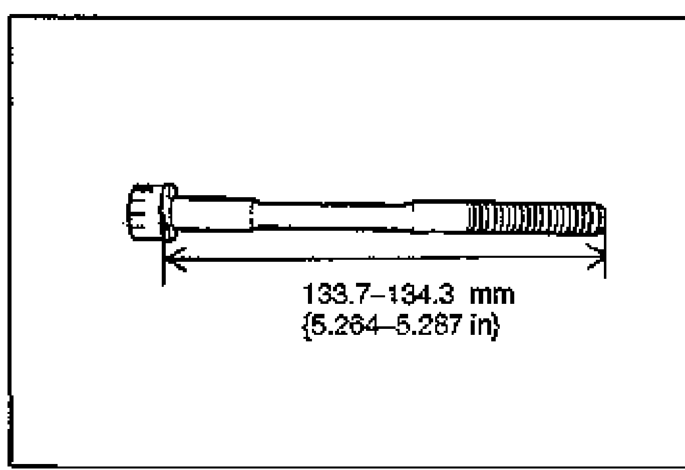
- 2Apply clean engine oil to the threads and the seat face of each bolt, and install them and the washers.
- 3Tighten the bolts in two or three steps in the order shown.
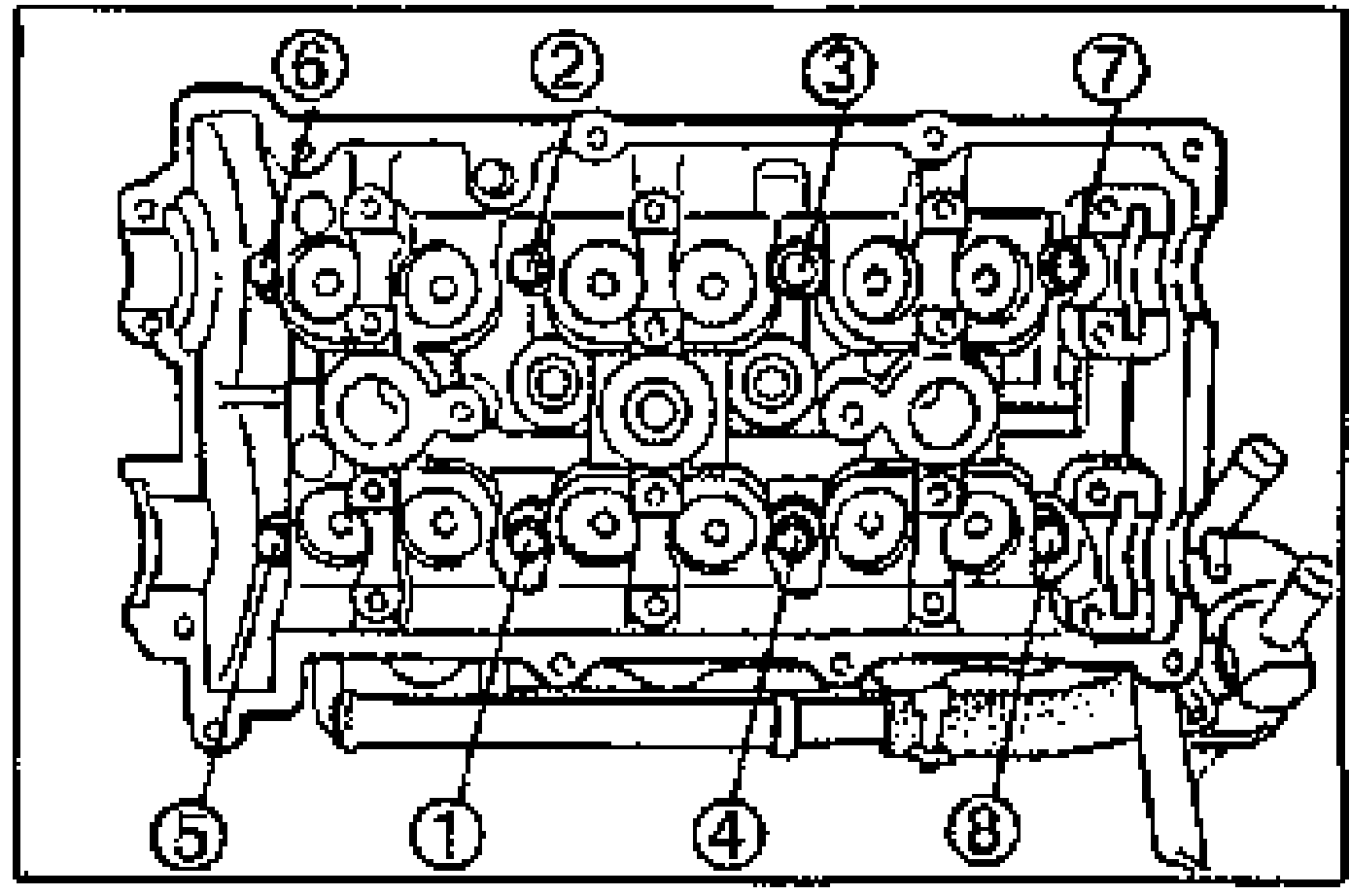
- 4Put a paint mark on each bolt head.
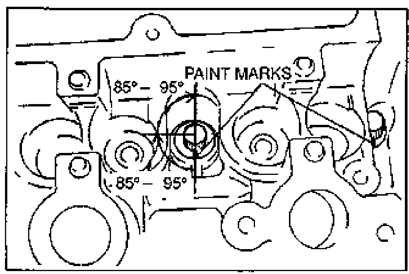
- 5Using the marks as a reference, tighten the bolts by turning each 85°-95° in the sequence shown.
- 6Further tighten each bolt by turning another 85°-95°.
| Specification | Value |
|---|---|
| Oil control plug projectionstep 1 | 8.0-9.0mm {0.315-0.354 in} |
| Cylinder head bolt lengthmeasured before installation | 133.7-134.3mm {5.264-5.287 in} |
| Cylinder head bolt maximum lengthreplace if exceeded | 135.0mm {5.315 in} |
| Tightening torque (cylinder head bolts)step 8-(3) | ≈227 - 254N·m |
Oil control plug projectionstep 1
8.0-9.0mm {0.315-0.354 in}
Cylinder head bolt lengthmeasured before installation
133.7-134.3mm {5.264-5.287 in}
Cylinder head bolt maximum lengthreplace if exceeded
135.0mm {5.315 in}
Tightening torque (cylinder head bolts)step 8-(3)
227 - 254N·m