
INSTALLATION
B2-121prose procedureStep 3 Torque specifications
| Specification | Value |
|---|---|
| 32 - 46N·m | |
| upper right | 16 - 22N·m |
| 43 - 61N·m | |
| right | 44 - 60N·m |
| Torque (SELF LOCK NUT, NEW) | 41 - 54N·m |
| right | 44 - 58N·m |
| 43 - 56N·m | |
| lower center | 44 - 58N·m |
| lower center | 44 - 60N·m |
| lower left | 16 - 22N·m |
| lower left bolt | 94 - 126N·m |
32 - 46N·m
upper right
16 - 22N·m
43 - 61N·m
right
44 - 60N·m
Torque (SELF LOCK NUT, NEW)
41 - 54N·m
right
44 - 58N·m
43 - 56N·m
lower center
44 - 58N·m
lower center
44 - 60N·m
lower left
16 - 22N·m
lower left bolt
94 - 126N·m
NOTE
Gaskets and split pin shown in the figure are to be replaced with new ones (GASKET, NEW; SELF LOCK NUT, NEW; SPRIT PIN, NEW).
Drive shaft
- 1Apply grease to the end of the drive shafts.The oil seals are damaged easily if this procedure is not done correctly.
- 2Install a new clip with the end gap facing upward.
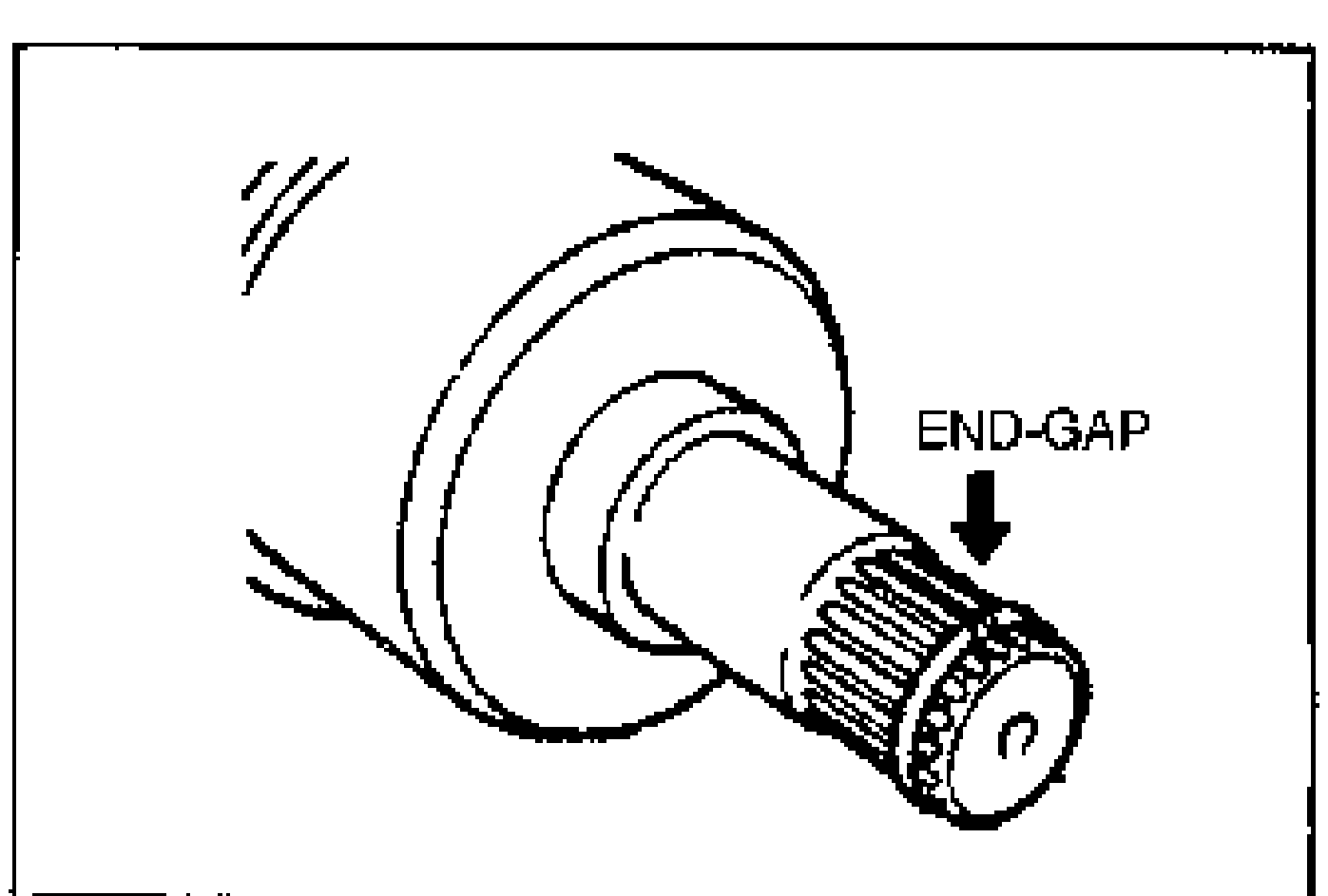
- 3Install the drive shaft.
- 4Push the drive shaft into the joint shaft.
- 5Install the joint shaft.
- 6Tighten the bolts in the order shown.
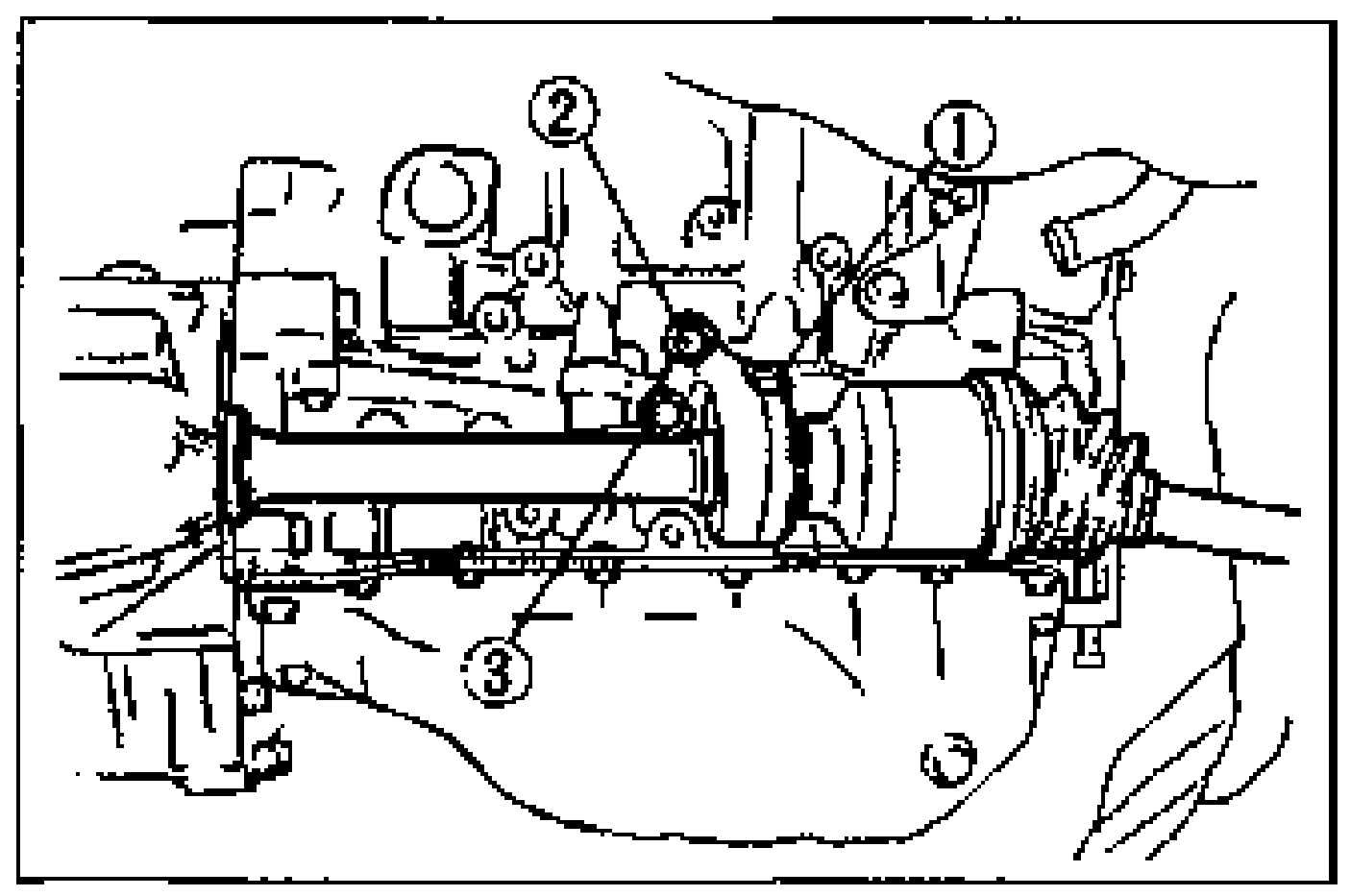
- 7After installation, pull the front hub outward to confirm that the drive shaft is securely held by the clip.
| Specification | Value |
|---|---|
| Tightening torque (joint shaft bolts)Drive shaft step 6 | 43 - 61N·m |
Tightening torque (joint shaft bolts)Drive shaft step 6
43 - 61N·m