
Inspection / Repair - Valve Guide / Valve Seat
B2-76prose procedureReplacement of valve guide (continued)
- 4Tap the valve guide in from the side opposite the combustion chamber until the SST contacts the cylinder head.
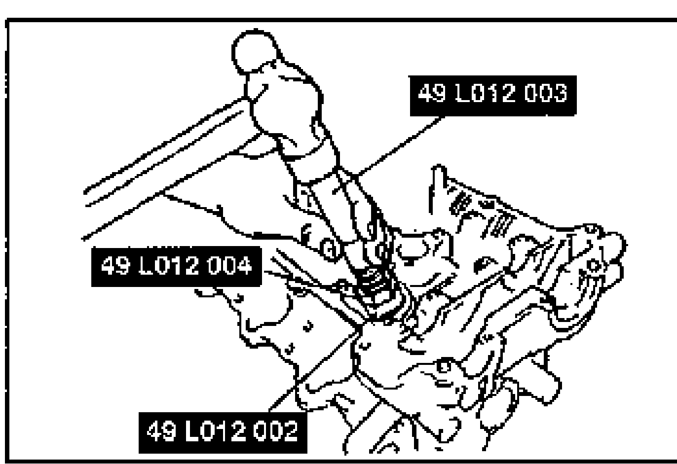
- 5Verify that the valve guide projection height is within the specification. (Refer to page B2-75.)
- 6If not, repeat steps 2-4.
Valve Seat
- 1Inspect the contact surface of each valve seat and valve face for the following: (1) Roughness; (2) Damage.
- 2If necessary, resurface the valve seat by using a 45° valve seat cutter and/or resurface the valve face.
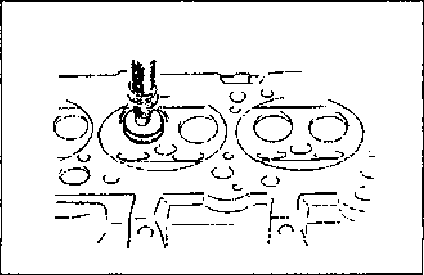
- 3Apply a thin coat of Prussian blue to the valve face.
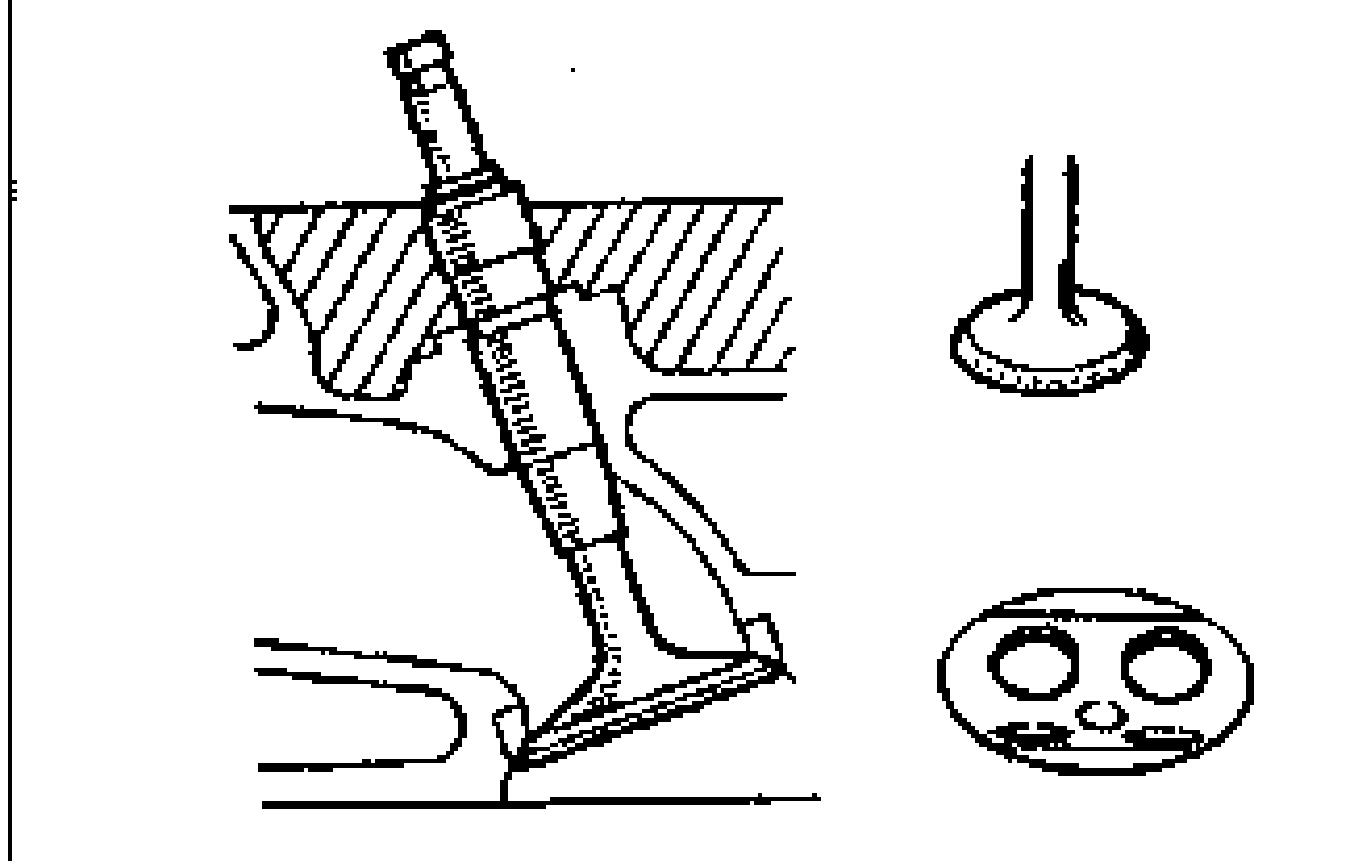
- 4Check the valve seating by pressing the valve against the seat. (1) If blue does not appear 360° around the valve face, replace the valve. (2) If blue does not appear 360° around the valve seat, resurface the seat.
- 5Measure the seat contact width.
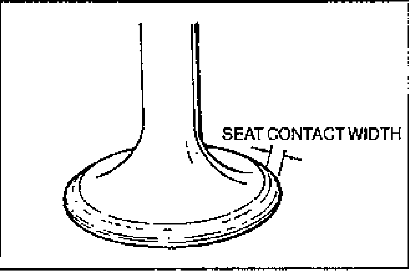
- 6Verify that the valve seating position is at the center of the valve face. (1) If the seating position is too high, correct the valve seat with a 75° cutter. (2) If the seating position is too low, correct the valve seat with a 45° cutter.
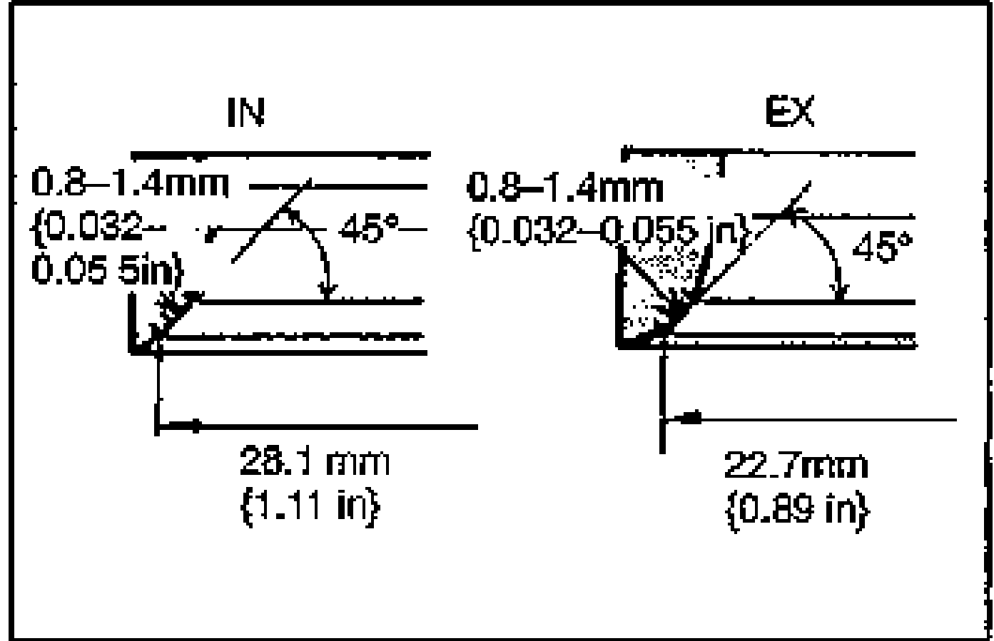
- 7Seat the valve to the valve seat by using lapping compound.
| Specification | Value |
|---|---|
| Width (seat contact) | 0.8-1.4 {0.032-0.055}mm {in} |
| Seat diameterIN | 28.1 {1.11}mm {in} |
| Seat diameterEX | 22.7 {0.89}mm {in} |
Width (seat contact)
0.8-1.4 {0.032-0.055}mm {in}
Seat diameterIN
28.1 {1.11}mm {in}
Seat diameterEX
22.7 {0.89}mm {in}