
ASSEMBLY — Valve Seal / Valve and Valve Spring / Cylinder Head
B2-101prose procedureK8-ZE V6 cylinder head assembly procedures.
Valve Seal (continued)
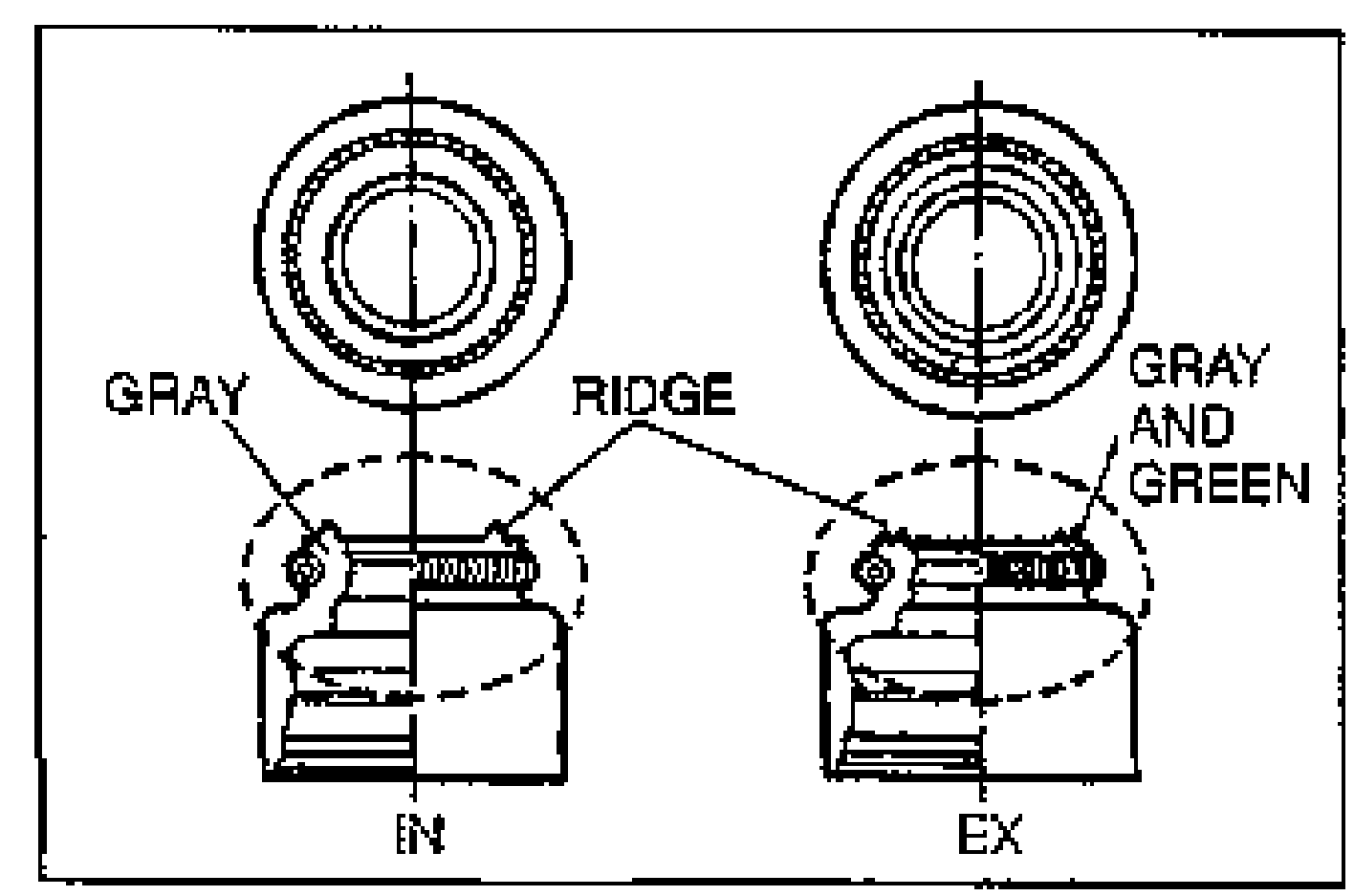
- 2Slide the valve seal onto the valve guide with the SST.The intake and exhaust valve seals are different as shown.
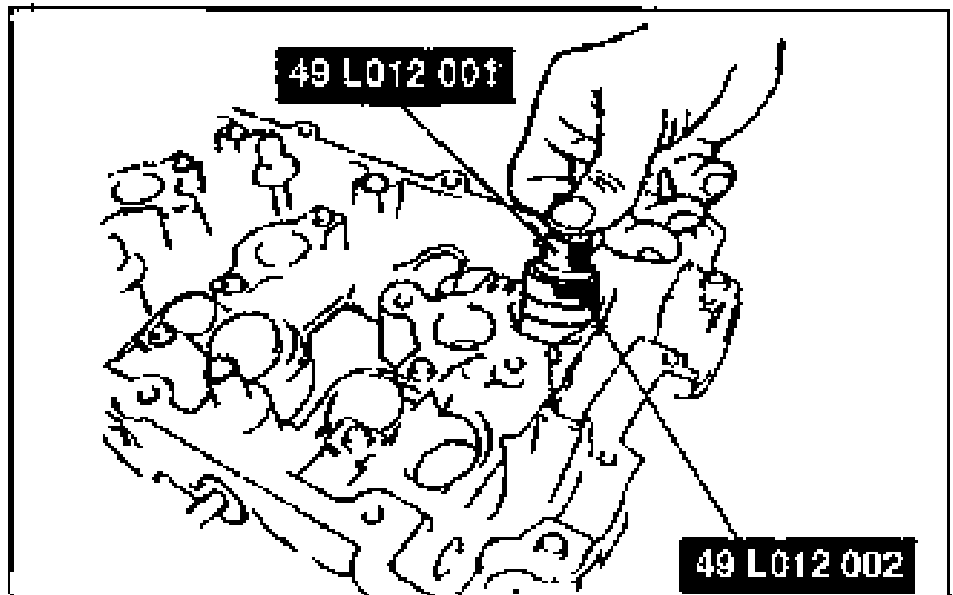
- 3Set the SST against the valve seal.Using a hammer will damage the valve seal.
- 4Using the SST, press the valve seal on by hand until the SST contacts the cylinder head.
Valve seal identification
Intake
RidgeNo or One
ColorGray
Exhaust
RidgeTwo
ColorGray or Green
Valve and Valve Spring
- 1Install the lower spring seat.
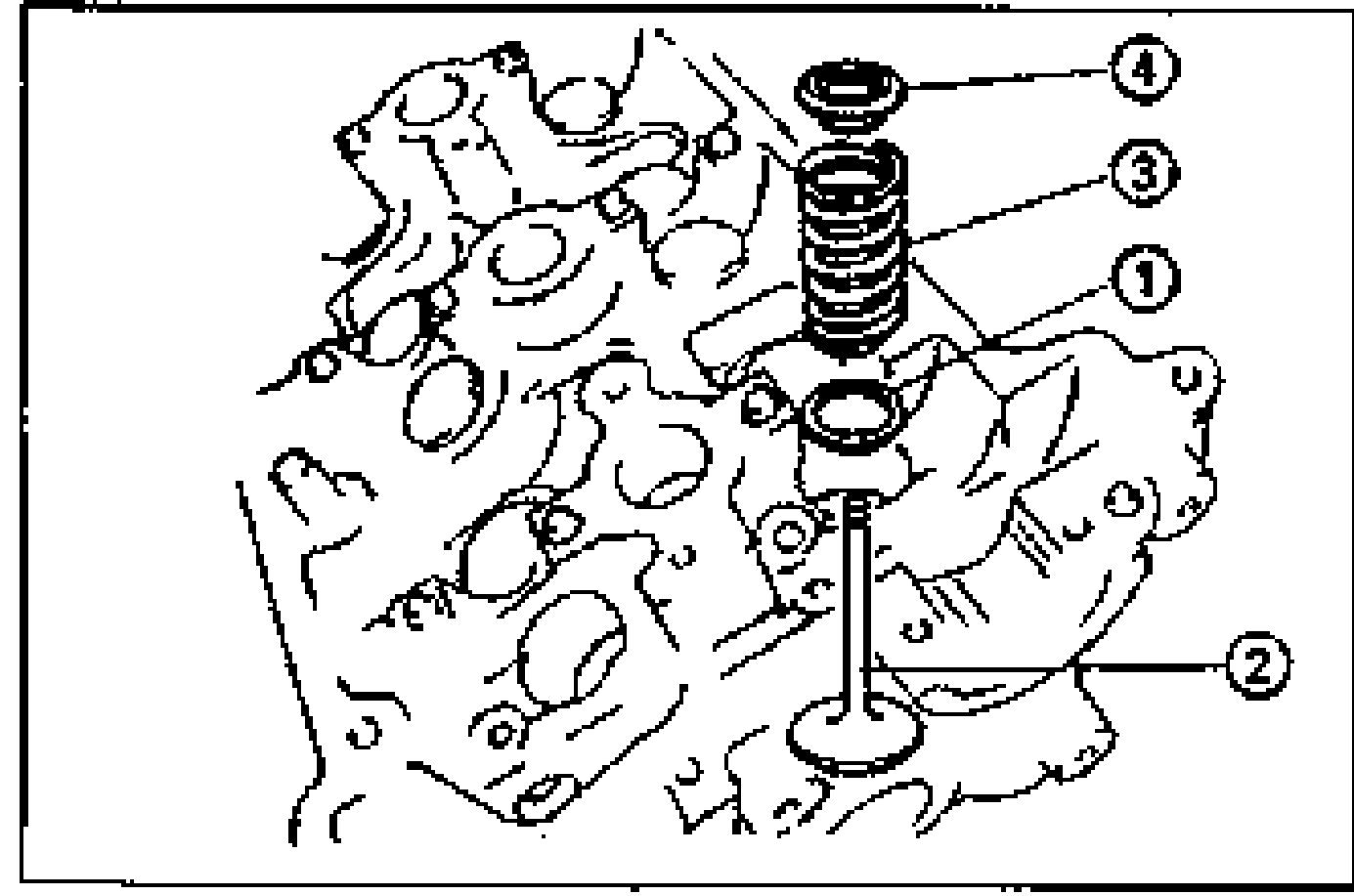
- 2Install the valve.
- 3Install the spring with the closer pitch toward the cylinder head.
- 4Install the upper spring seat.
- 5Compress the valve spring with the SST, and install the valve keepers.
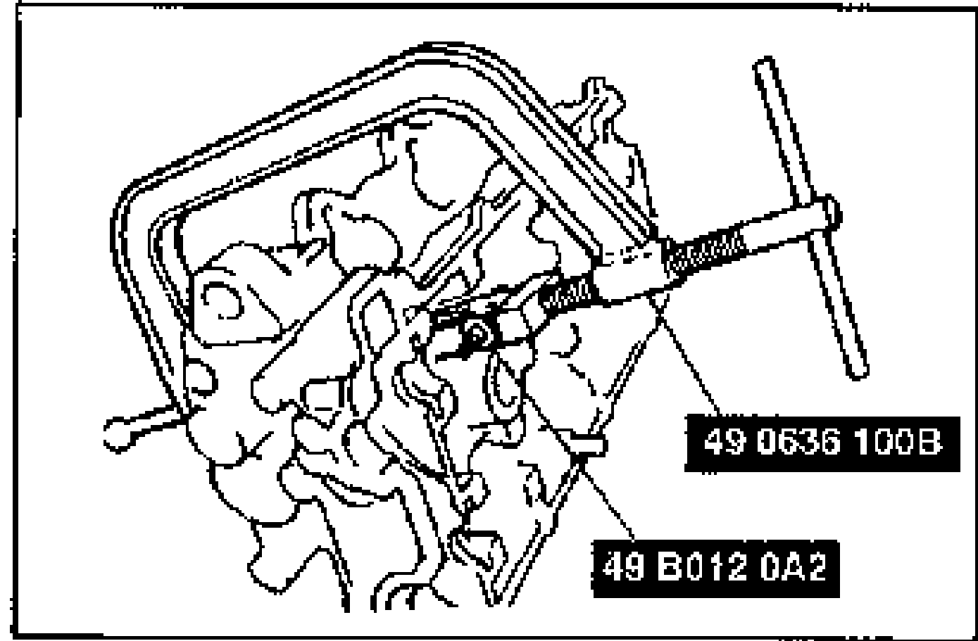
- 6Remove the SST.
- 7Tap the end of the valve stem lightly two or three times with a plastic hammer to verify that the keepers are fully seated.
Cylinder Head
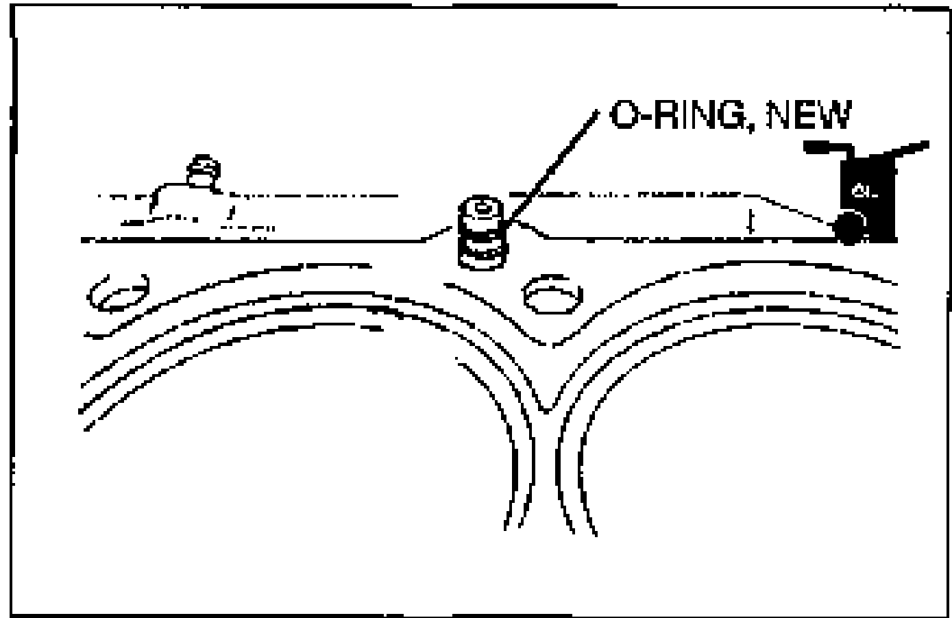
- 1Measure the amount of oil control plug projection from the deck of the cylinder block.
- 2Apply clean engine oil to new O-rings and install them to the oil control plugs.
| Specification | Value |
|---|---|
| Projection (A)Oil control plug projection from cylinder block deck | 8.0—9.0mm {0.315—0.354 in}mm |
Projection (A)Oil control plug projection from cylinder block deck
8.0—9.0mm {0.315—0.354 in}mm