
ASSEMBLY — HLA / Camshaft
B2-103prose procedureK8-ZE V6 — LH and RH heads; HLA hydraulic lash adjusters; camshaft thrust clearance is minimal so order matters.
HLA
- 1Apply clean engine oil to the friction surfaces.
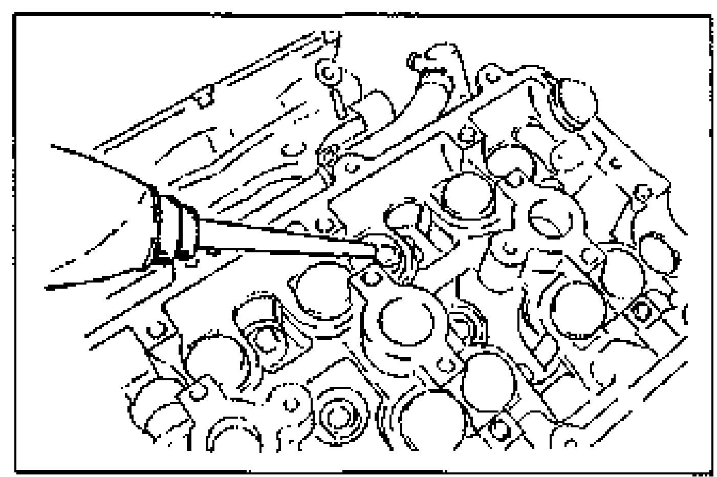
- 2If the HLA are being reused, install them in the positions from which they were removed.
- 3Verify that the HLA move smoothly in their bores.
Camshaft
CAUTION
Camshafts must be assembled in the following procedure. Otherwise, camshaft can be broken or damaged because there is little camshaft thrust clearance.
Camshaft
- 1Apply clean engine oil to the camshaft journals and the supports.
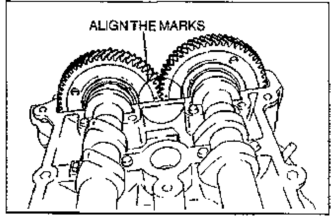
- 2Install the camshafts so that the intake camshaft gear mark and exhaust camshaft gear mark align.
- 3Remove the oil, dirt from the mating surfaces between the front camshaft cap and the cylinder head, and degrease.
- 4Apply a light coat of silicone sealant to the shaded areas as shown.
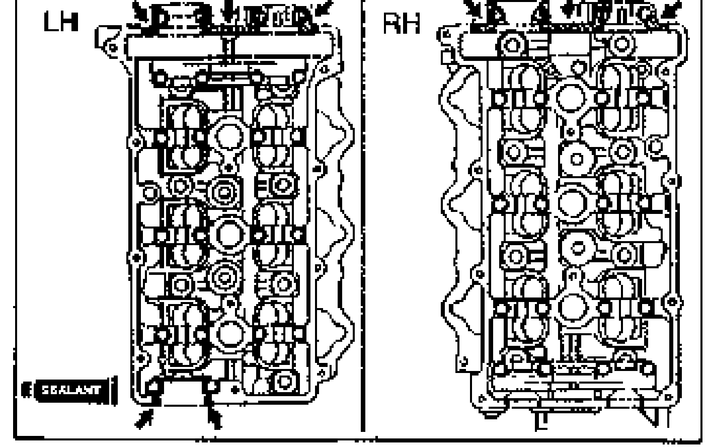
- 5Install the thrust caps onto the cylinder heads. Hand tighten the bolts in five or six steps in the order shown, until the thrust caps fully seated on the cylinder heads.
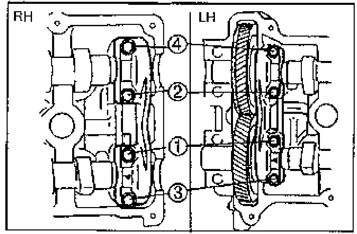
- 6Install the camshaft caps and hand tighten the bolts.
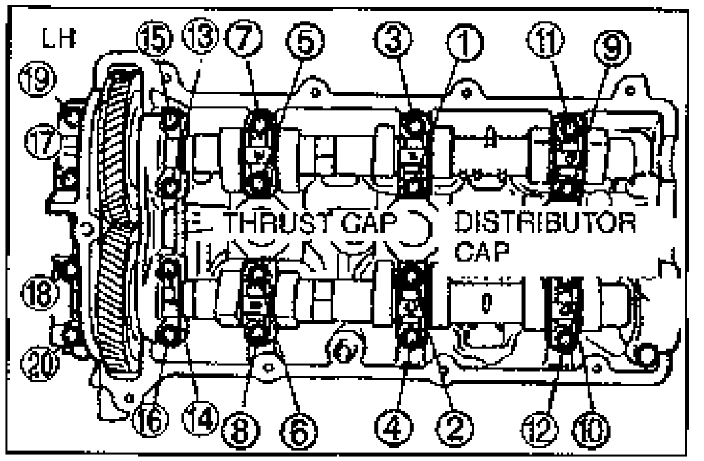
- 7Tighten the camshaft cap bolts in five or six steps in the order shown.Tightening torque: 11.3—14.2 N·m {115—145 kgf·cm, 100—125 in·lbf}
- 8Retighten the bolts in the order shown.Tightening torque: 11.3—14.2 N·m {115—145 kgf·cm, 99.9—125 in·lbf}
| Specification | Value |
|---|---|
| Camshaft cap bolt tightening torque (step 7) | 11.3 - 14.2N·m |
| Camshaft cap bolt retightening torque (step 8) | 11.3 - 14.2N·m |
Camshaft cap bolt tightening torque (step 7)
11.3 - 14.2N·m
Camshaft cap bolt retightening torque (step 8)
11.3 - 14.2N·m