
AIR CONDITIONER — Component Location (continued)
G-75component photoFull-auto air conditioner variant (G4 callout series; includes air-intake and air-flow-mode actuators not present in the manual A/C G2/G3 diagrams).
Component LocationFig. fig1
Full-auto A/C component locations: heater control unit (G4-01), air-flow-mode actuator (G4-02), air-intake actuator (G4-03), blower relay (G4-04), refrigerant pressure switch (G4-05), resistor (G4-06), fan switch (G4-07), circuit breaker rear heater (G4-08), thermoswitch (G4-09), connectors G4-10/G4-11, main fuse block (X-01), ignition switch (X-03), connectors X-07/X-08/X-17, and join box connectors JB-07/JB-06/JB-02.
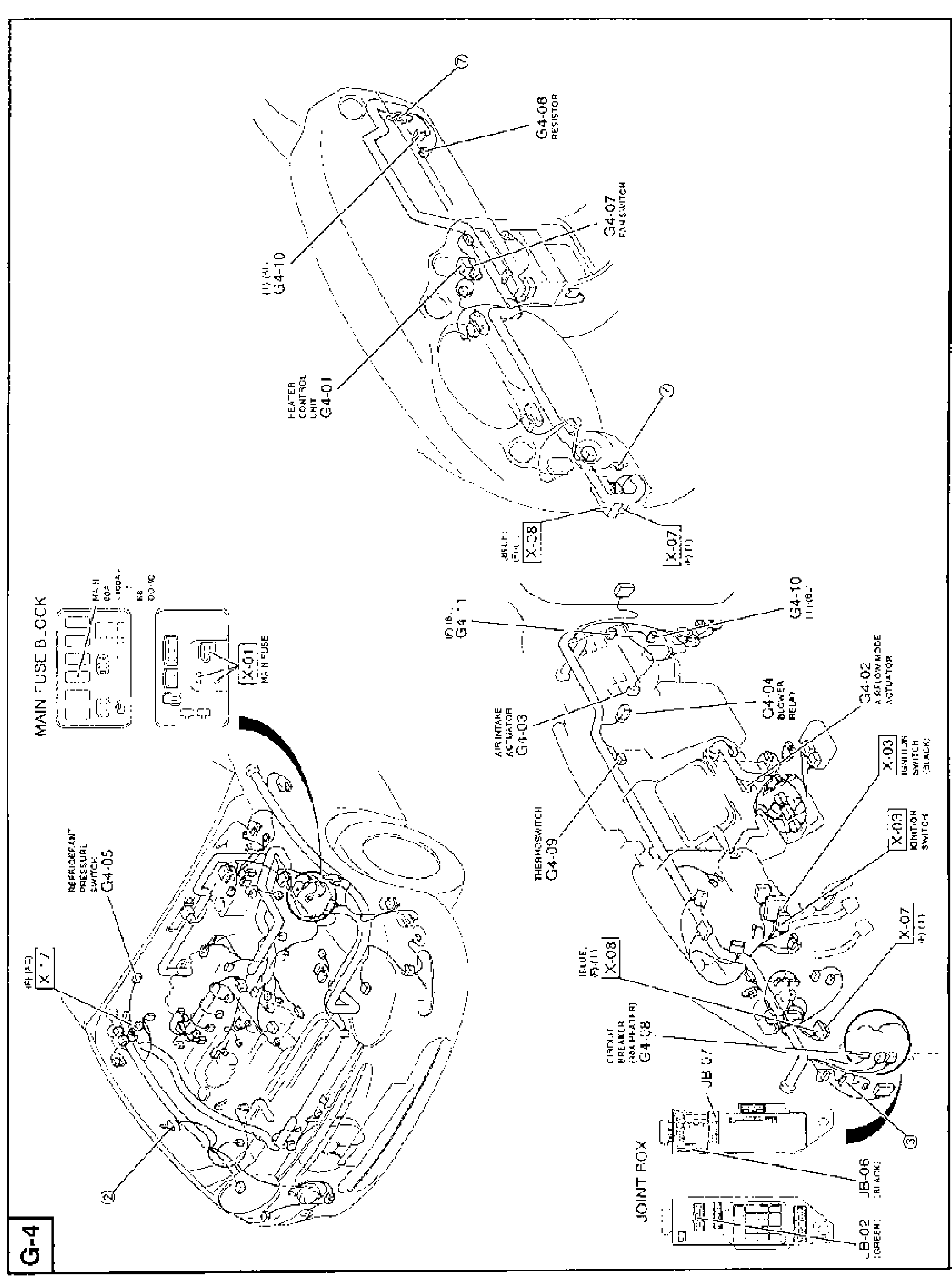
G-4
1G4-01(Heater control unit)
2G4-02(Air-flow-mode actuator)
3G4-03(Air-intake actuator)
4G4-04(Blower relay)
5G4-05(Refrigerant pressure switch)
6G4-06(Resistor)
7G4-07(Fan switch)
8G4-08(Circuit breaker (rear heater))
9G4-09(Thermoswitch)
10G4-10(Connector)
11G4-11(Connector)
12X-01(Main fuse)
13X-03(Ignition switch (Black))
14X-07(Connector)
15X-08(Connector (Blue))
16X-17(Connector)
17JB-07(Join box connector)
18JB-06(Join box connector (Black))
19JB-02(Join box connector (Green))