
AIR CONDITIONER — REFRIGERANT SYSTEM SERVICE PROCEDURES (Charging continued)
G-51prose procedureREFRIGERANT SYSTEM SERVICE PROCEDURES
Charging (continued)
- 16Close the high-pressure side valve of the manifold gauge.
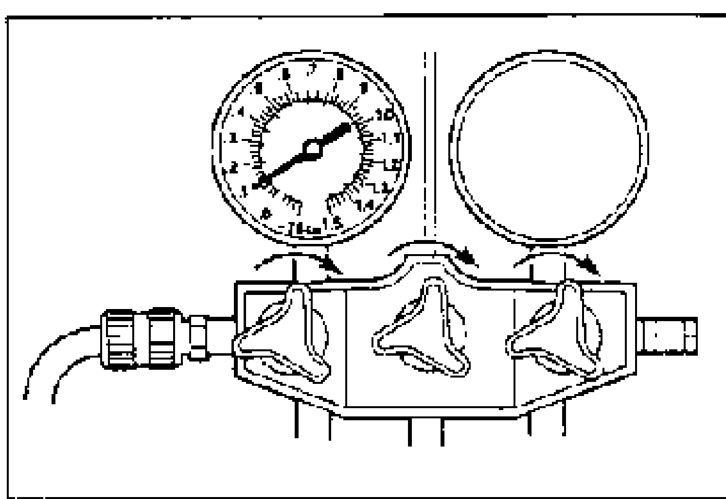
- 17Check for leaks by using a gas leak tester. If there are no leaks, go to step 18. If a leak is found at a loose joint, tighten the joint and check for leaks again. If there is still a leak at the same joint, discharge the refrigerant and then repair the joint. Repeat the charging procedure from step 9. If there are no leaks after tightening the joint, go to step 18.
- 18Open the high-pressure side valve of the manifold gauge and charge with half the regular amount of refrigerant.
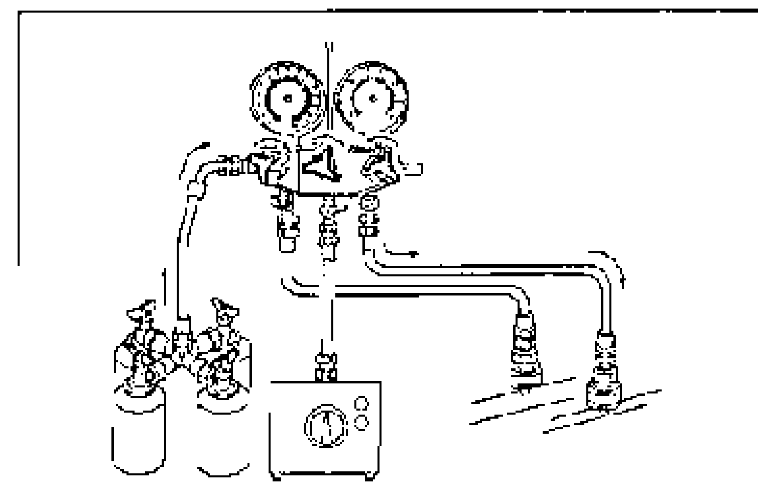
- 19Close the high-pressure side valve of the manifold gauge.Running the engine with the high-pressure side valve open is dangerous. Pressure within the service cans will increase and the cans could explode, scattering metal fragments and liquid refrigerant that can seriously injure you. Therefore, do not open the high-pressure side valve while the engine is running.
- 20Start the engine and actuate the A/C compressor.
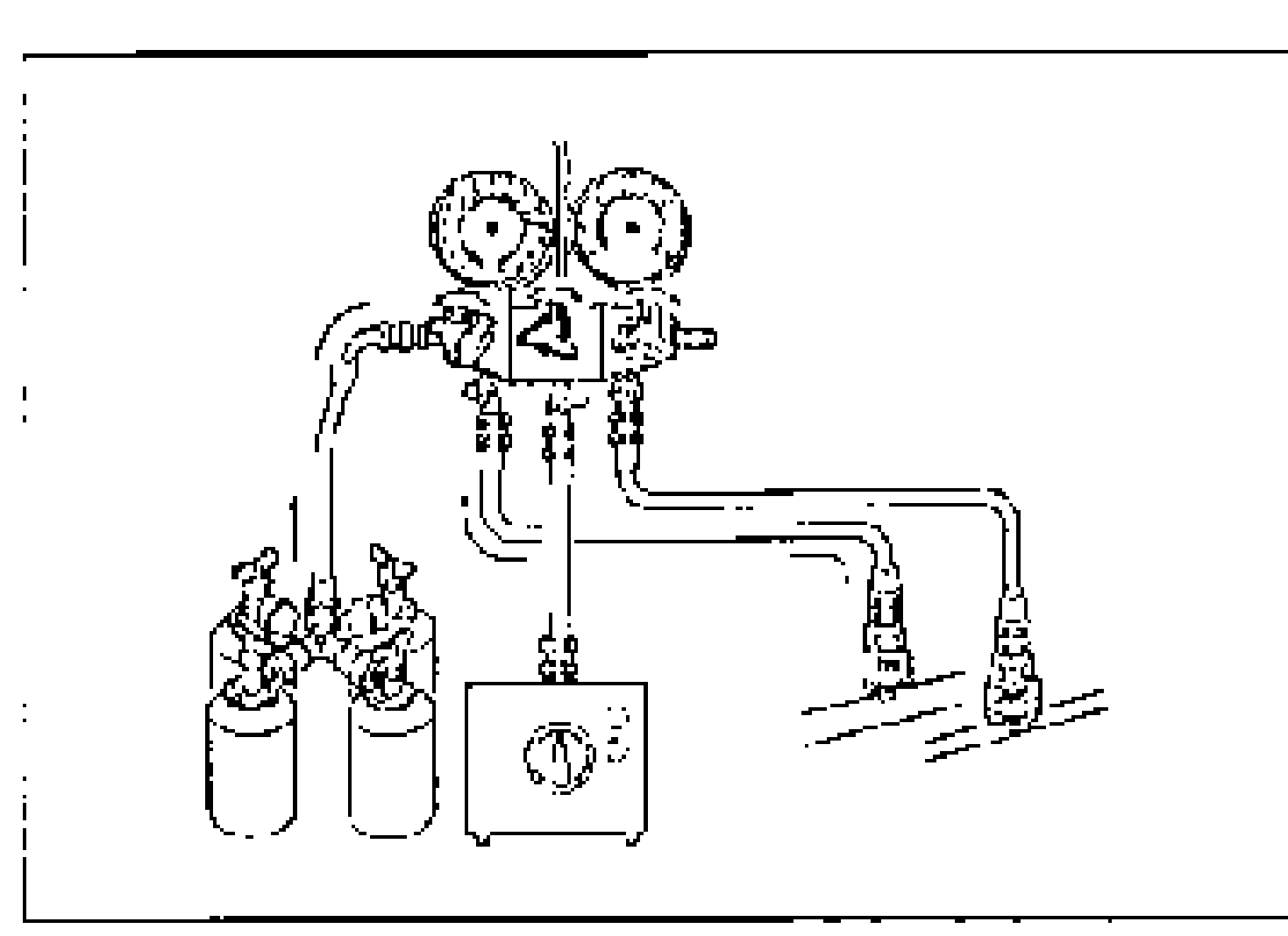
- 21Open the low pressure side valve of the gauge set and charge with the remaining refrigerant.
- 22Close the low-pressure side valve of the manifold gauge.
- 23Stop the engine and A/C compressor.
- 24Check for leaks by using a gas leak tester. If there are no leaks, go to step 25. If a leak is found at a loose joint, tighten the joint and check for leaks again. If there is still a leak at the same joint, discharge the refrigerant and then repair the joint. Repeat the charging procedure from step 9. If there are no leaks after tightening the joint, go to step 25.
- 25Disconnect the high- and low-pressure side quick couplers from the charging valves.
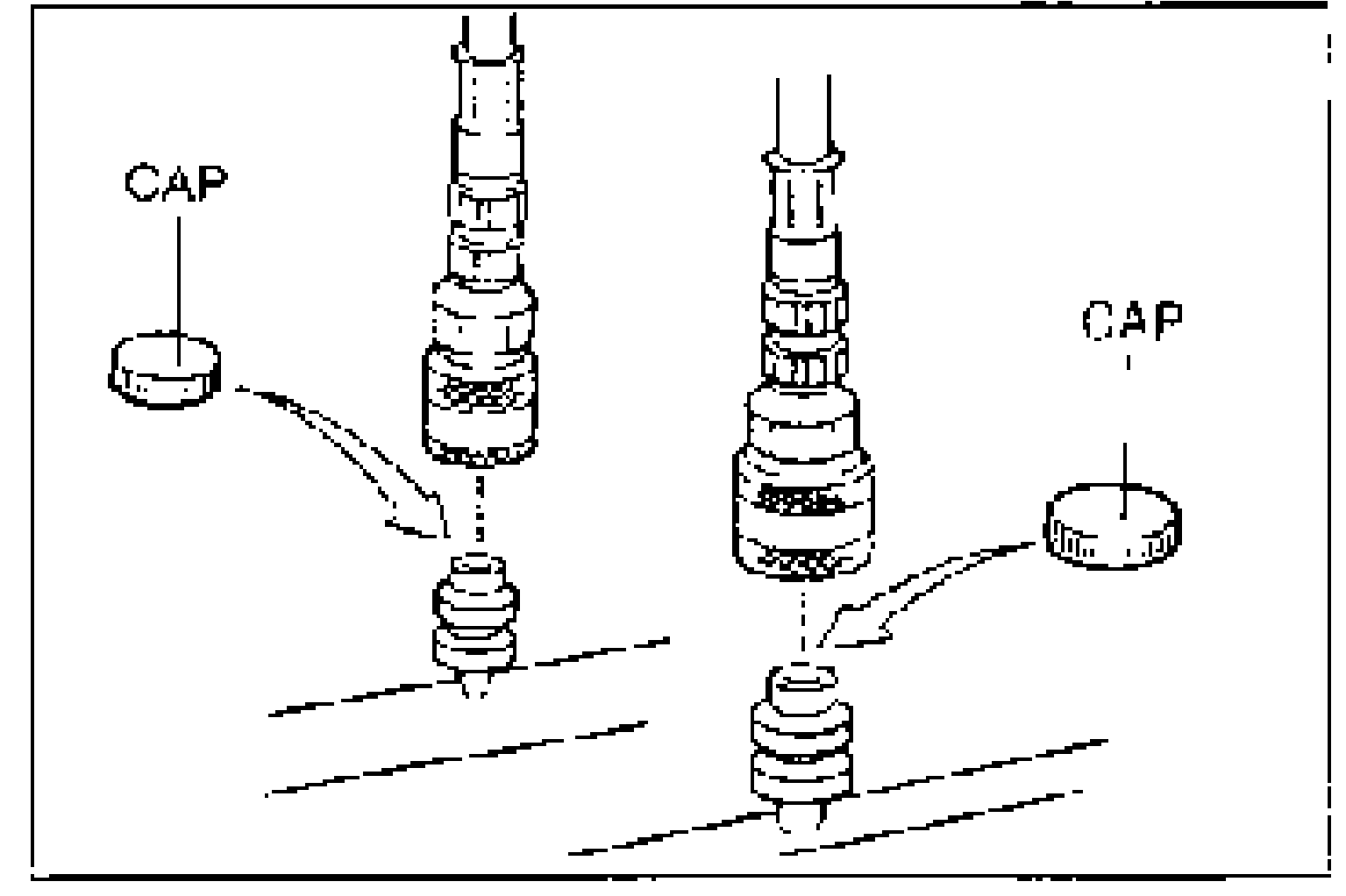
- 26Install the caps to the charging valves.
WARNING
Running the engine with the high-pressure side valve open is dangerous. Pressure within the service cans will increase and the cans could explode, scattering metal fragments and liquid refrigerant that can seriously injure you. Therefore, do not open the high-pressure side valve while the engine is running.