Mazda MX-3 silhouetteMX-3

HEATER - STRUCTURAL VIEW

G-36component photo

Heater control panel comes in LOGIC TYPE (push-button) and WIRE TYPE (lever) variants.

STRUCTURAL VIEW

Component LocationFig. fig1

Structural view of the heater system showing heater unit, blower unit, and heater control unit with their service-page references.
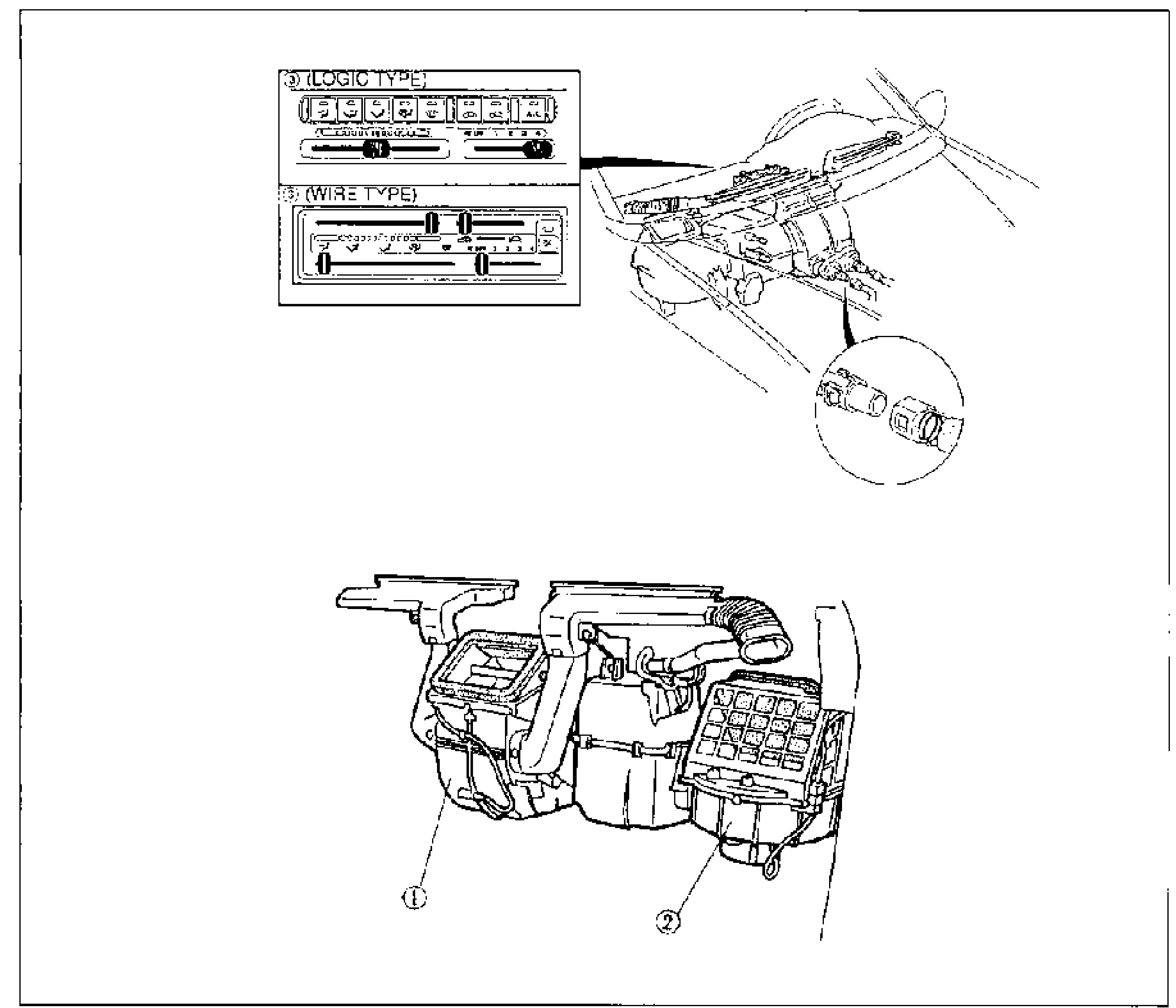
Structural view of the heater system. Top-left insets show the heater control panel for (3) LOGIC TYPE (push-button mode/recirc controls with two sliders) and (3) WIRE TYPE (lever-type control with sliders). Top-right shows the dash/wiring routing with a connector detail. Lower center shows the heater unit and blower unit assembly. Numbered callouts: 1 = Heater unit, 2 = Blower unit, 3 = Heater control unit.
11(Heater unit)
22(Blower unit)
33(Heater control unit)

Component index

1
ComponentHeater unit
ProcedureRemoval / Installation
1
ComponentHeater unit
ProcedureDisassembly / Inspection / Assembly
1
ComponentAirflow mode actuator
ProcedureInspection
2
ComponentBlower unit
ProcedureRemoval / Installation
2
ComponentBlower unit
ProcedureDisassembly / Assembly
2
ComponentBlower motor (in blower unit)
ProcedureInspection
2
ComponentResistor (in blower unit)
ProcedureInspection
2
ComponentAir intake actuator
ProcedureInspection
2
ComponentBlower relay
ProcedureRemoval / Installation
2
ComponentBlower relay
ProcedureInspection
3
ComponentHeater control unit
ProcedureRemoval / Installation
3
ComponentHeater control unit
ProcedureDisassembly / Assembly
3
ComponentHeater control unit
ProcedureInspection
3
ComponentAir intake wire
ProcedureAdjustment
3
ComponentAirflow mode wire
ProcedureAdjustment
3
ComponentAir mix wire
ProcedureAdjustment

Search Manual

Search pages, specs, and procedures