
BLOWER MOTOR / RESISTOR / AIR INTAKE ACTUATOR / BLOWER RELAY
G-42prose procedureResistor terminal table lists alternate terminal letters in parentheses for the wire-type variant, e.g. A (D).
Inspection
Blower Motor Inspection
- 1Disconnect the blower motor connector.
- 2Connect battery positive voltage to terminal A and ground to terminal B of the blower motor. Verify that the motor operates.
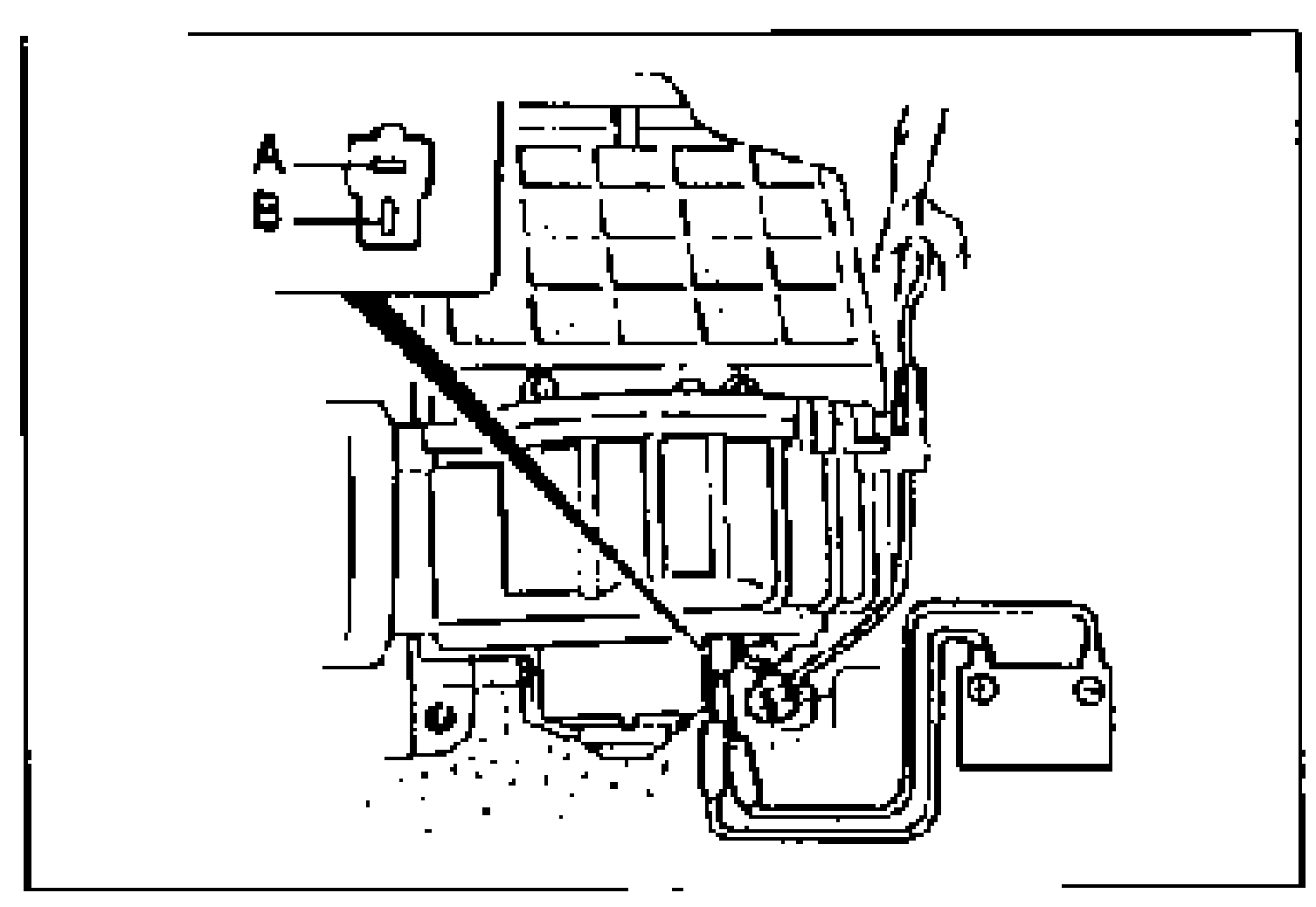
- 3If not as specified, replace the blower motor. (Refer to page G-41.)
RESISTOR
Inspection
Resistor Inspection
- 1Disconnect the resistor connector.
- 2Check for continuity between the resistor terminals.
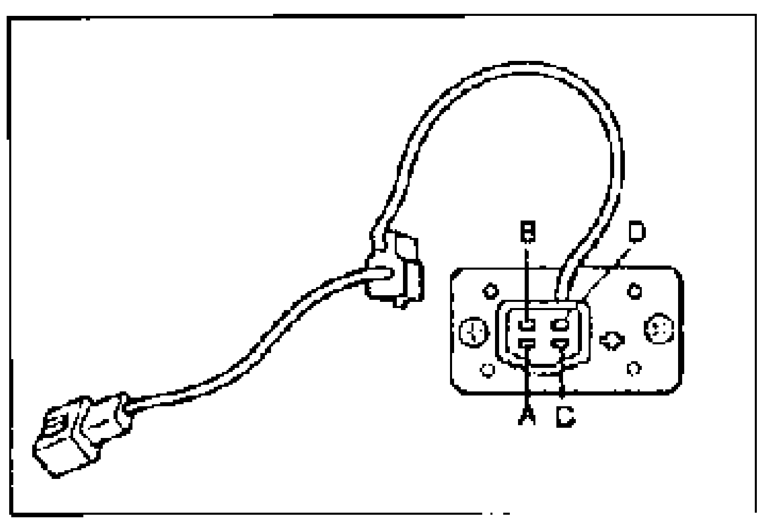
- 3If not as specified, replace the resistor. (Refer to page G-41.)
Resistor terminal continuity (O—O: Continuity; ( ): Wire type)
O—O
B (C)O
C (A)
D (B)
O
B (C)
C (A)O
D (B)
O
B (C)
C (A)
D (B)O
NOTE
O—O : Continuity ( ) : Wire type
AIR INTAKE ACTUATOR
Inspection
Air Intake Actuator Inspection
- 1Disconnect the air intake actuator connector.
- 2Connect battery positive voltage to the following terminals and check the operation of the air intake actuator.B+: Battery positive voltage
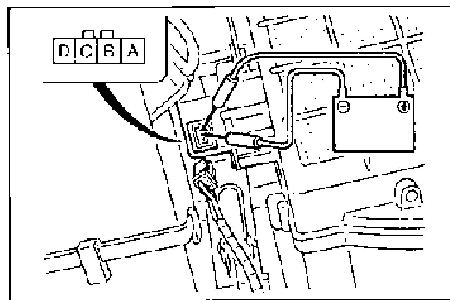
- 3If not as specified, replace the air intake actuator. (Refer to page G-41.)
Air intake actuator operation (B+: Battery positive voltage)
D
GNDC
Actuator operationREC → FRESH
D
GNDA
Actuator operationFRESH → REC
BLOWER RELAY
Removal / Installation
Blower Relay Removal / Installation
- 1Remove the blower unit. (Refer to page G-40.)
- 2Disconnect the blower relay connector.
- 3Remove the blower relay from the blower unit.
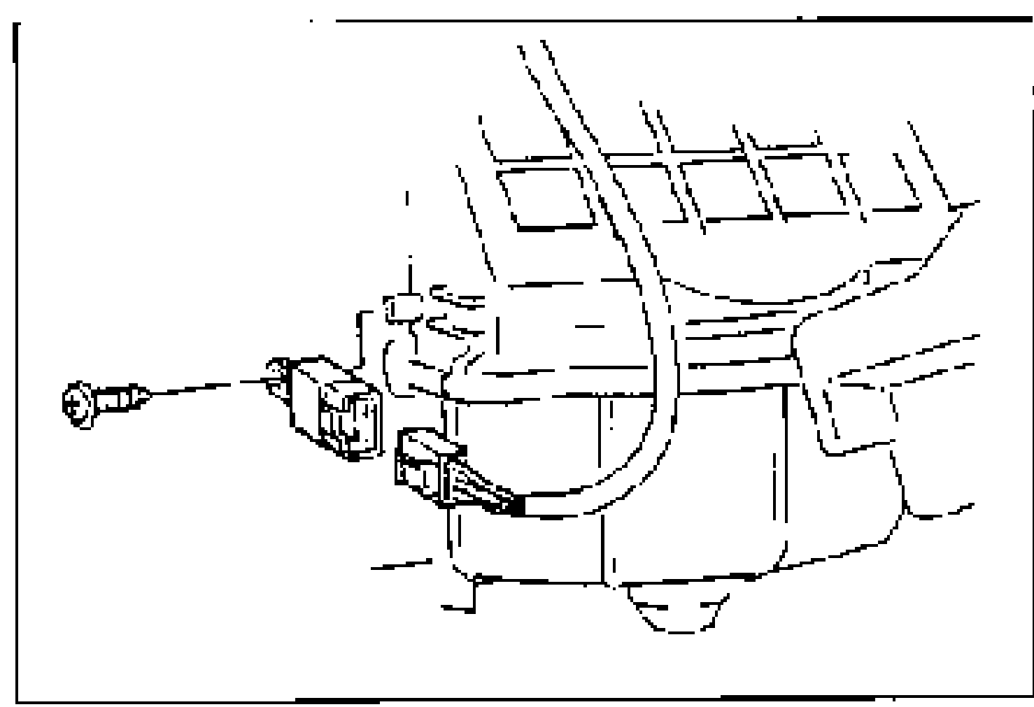
- 4Install in the reverse order of removal.
Inspection
Blower Relay Inspection
- 1Remove the blower relay.
- 2Check for continuity between the relay terminals.B+: Battery positive voltage
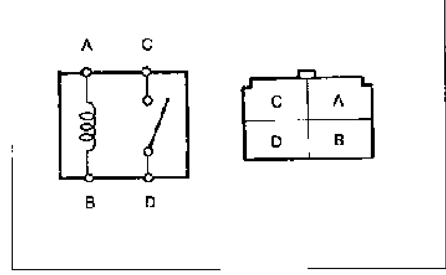
- 3If not as specified, replace the blower relay.
Blower relay terminal continuity (B+: Battery positive voltage; O—O: Continuity)
—
GND (Connection)—
AO
BO
C
D
A
GND (Connection)B
A
B
CO
DO
NOTE
O—O : Continuity