
TROUBLESHOOTING
G-24wiring diagramFlowchart No. 6 is B6-specific; B6 uses a single condenser fan relay and A/D FAN 20A fuse (vs K8's 40A and multiple relays).
Flowchart No. 6
6
DetailSymptom: Condenser fan does not operate, but magnetic clutch operates normally [B6]
6
DetailRelated components: Condenser fan relay, condenser fan, wiring harness
Condenser fan circuit [B6]
Components (5)
A/D FAN 20A fuseA/C relayCondenser fan relayCondenser fan motorGROUND
Connections (5)
A/D FAN 20A fuse
A/D FAN 20A fuse:+BCondenser fan relay:contactBlue with Yellow stripe
A/C relay
A/C relay:outCondenser fan relay:coilRed
Condenser fan relay
Condenser fan relay:coil-outGROUND:GNDBlack
Condenser fan relay:contact-outCondenser fan motor:M1Black with Blue stripe
Condenser fan motor
Condenser fan motor:M2GROUND:GNDBlack
Step 1
- 1Start the engine.
- 2Turn the fan switch and A/C switch on.
- 3Measure the voltage at the following terminal wires of the condenser fan relay connector.B+: Battery positive voltage
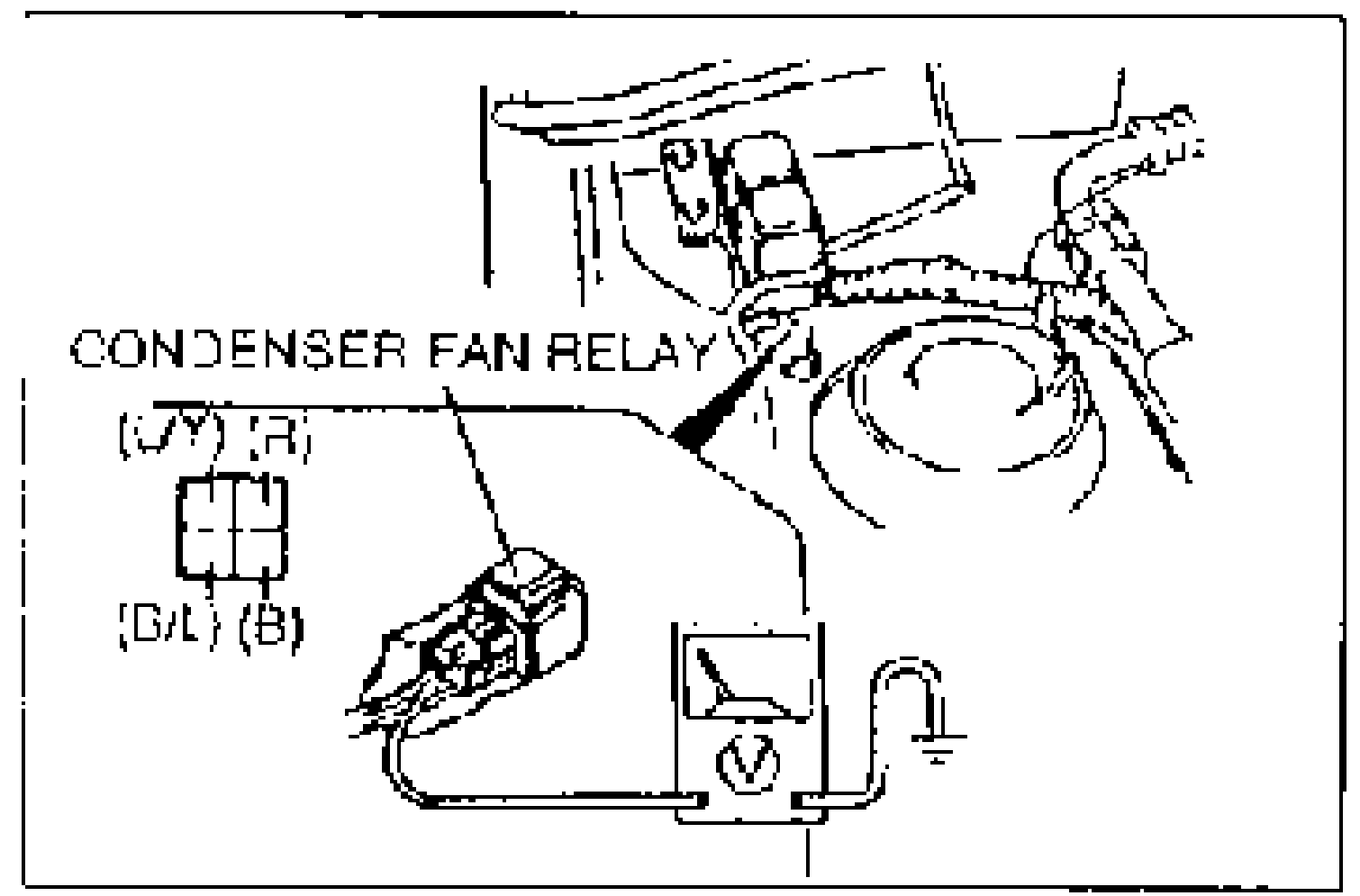
Wire / Voltage / Action (Step 1)
(R)
VoltageB+
ActionMeasure voltage at (B) wire
(R)
VoltageOther
ActionRepair wiring harness (A/C relay—Condenser fan relay)
(B)
Voltage0V
ActionMeasure voltage at (L/Y) wire
(B)
VoltageOther
ActionRepair wiring harness (Condenser fan relay—GND)
(L/Y)
VoltageB+
ActionMeasure voltage at (B/L) wire
(L/Y)
VoltageOther
ActionRepair wiring harness (A/D FAN 20A fuse—Condenser fan relay)
(B/L)
VoltageB+
ActionGo to Step 2
(B/L)
VoltageOther
ActionReplace condenser fan relay
Step 2
- 1Measure the voltage at the following terminal wires of the condenser fan connector.B+: Battery positive voltage
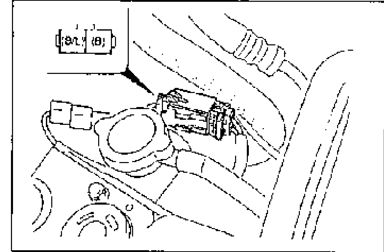
Wire / Voltage / Action (Step 2)
(B/L)
VoltageB+
ActionMeasure voltage at (B) wire
(B/L)
VoltageOther
ActionRepair wiring harness (Condenser fan relay—Condenser fan)
(B)
Voltage0V
ActionCheck condenser fan (Refer to page G-63)
(B)
VoltageOther
ActionRepair wiring harness (Condenser fan—GND)