
TROUBLESHOOTING
G-26prose procedureK8-specific two-speed condenser fan diagnostic continuation.
Step 1
- 1Connect a jumper wire between the (R/Y) terminal wire of the condenser fan relay No.2 connector and ground.
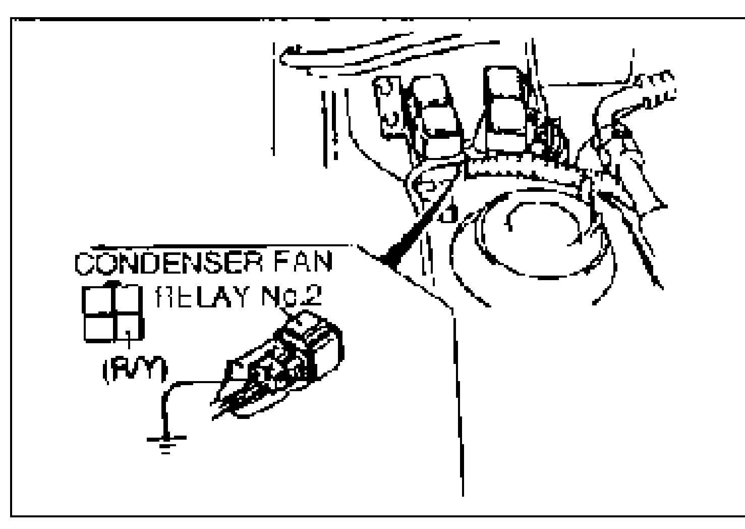
- 2Turn the ignition switch to ON.
- 3Verify that the condenser fan operates at high speed.
Condenser fan speed / Action (Step 1)
High
ActionCheck ECM (Refer to 1995 MX-3 Workshop Manual, section F2)
Low
ActionGo to Step 4
Does not operate
ActionGo to Step 2
Step 2
- 1Verify that the jumper wire is connected and the ignition switch is at ON.
- 2Measure the voltage at the (L) terminal wire of the condenser fan connector.B+: Battery positive voltage
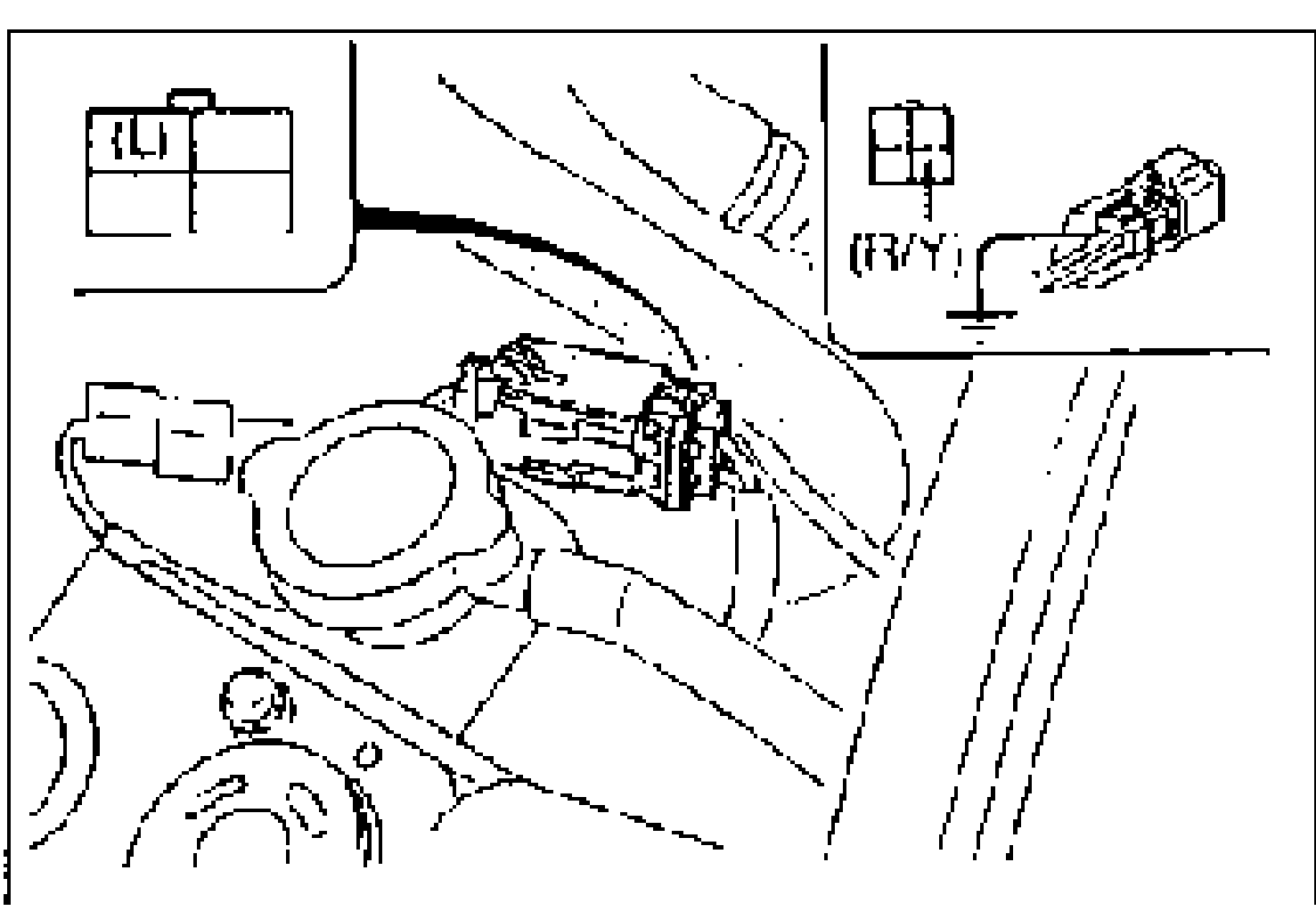
Voltage / Action (Step 2)
B+
ActionCheck condenser fan (Refer to page G-63)
Other
ActionGo to Step 3
Step 3
- 1Verify that the jumper wire is connected and the ignition switch is at ON.
- 2Measure the voltage at the following terminal wires of the condenser fan relay No.2 connector.B+: Battery positive voltage
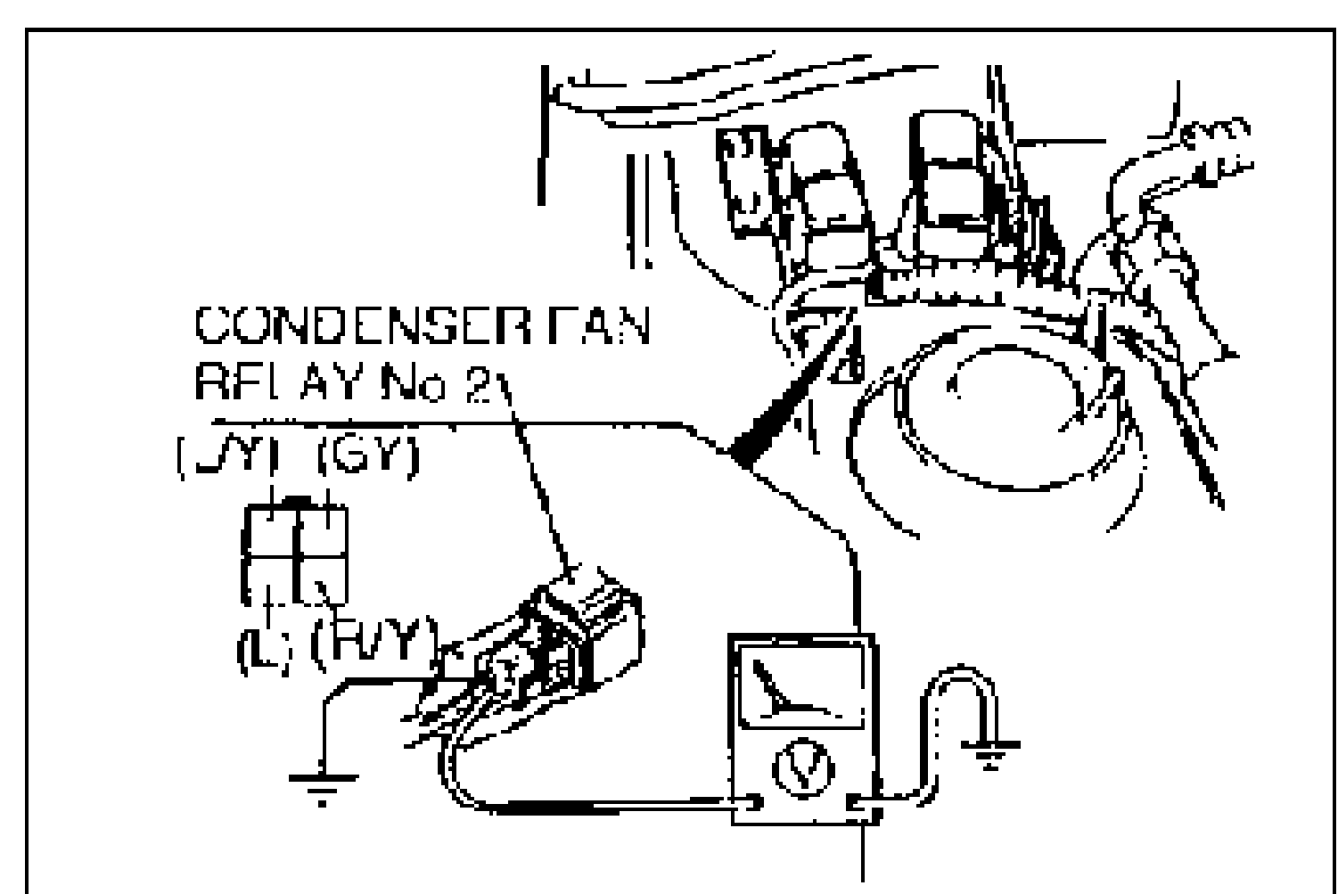
Wire / Voltage / Action (Step 3)
(GY)
VoltageB+
ActionMeasure voltage at (L/Y) wire
(GY)
VoltageOther
ActionRepair wiring harness (REAR WIPER 10A fuse—Condenser fan relay No.2)
(L/Y)
VoltageB+
ActionMeasure voltage at (L) wire
(L/Y)
VoltageOther
ActionRepair wiring harness (A/D FAN 40A fuse—Condenser fan relay No.2)
(L)
VoltageB+
ActionRepair wiring harness (Condenser fan relay No.2—Condenser fan)
(L)
VoltageOther
ActionReplace condenser fan relay No.2
Step 4
- 1Verify that the jumper wire is connected and the ignition switch is at ON.
- 2Measure the voltage at the (L/G) terminal wire of the condenser fan connector.B+: Battery positive voltage
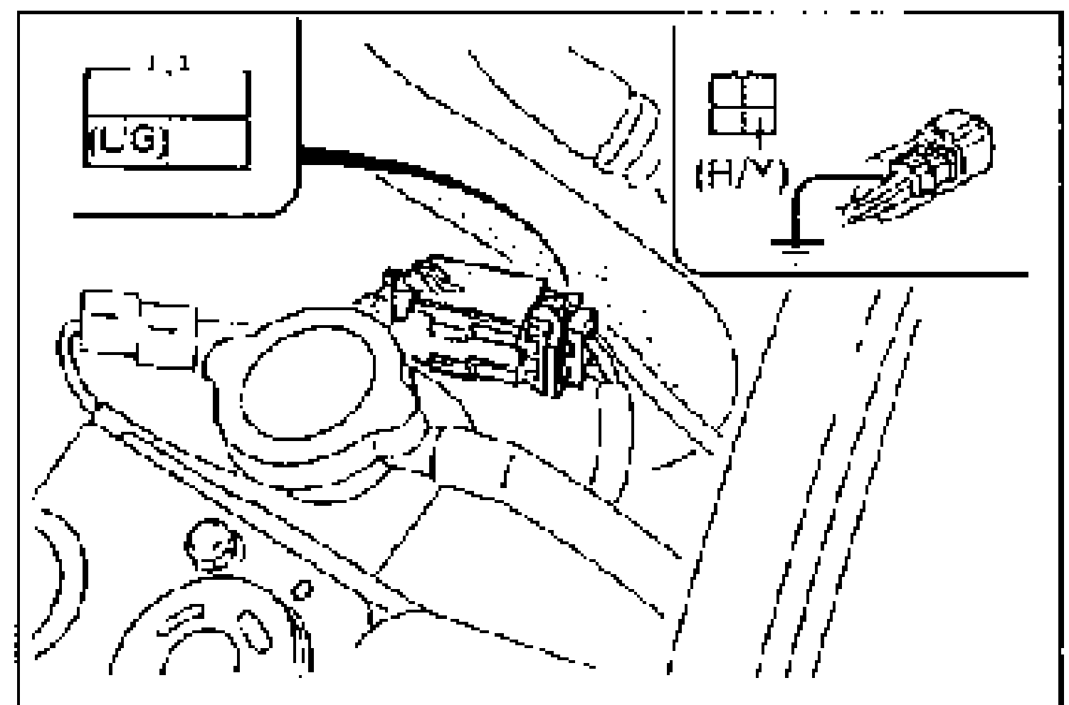
Voltage / Action (Step 4)
0V
ActionCheck condenser fan (Refer to page G-63)
Other
ActionGo to Step 5