
FLOWCHARTS — Flowchart No. 1 (continued): Steps 6–7
G-14flowchartTROUBLESHOOTING
Step 6
- 1Turn the fan switch off.
- 2Measure the voltage at the (L/W) terminal wire of the resistor connector.B+: Battery positive voltage
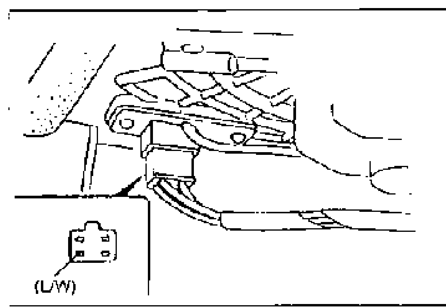
Step 6 — Resistor connector voltage
B+
ActionGo to Step 7
Other
ActionReplace resistor (Refer to page G-41)
Step 7
- 1Turn the ignition switch to OFF.
- 2Remove the heater control unit and disconnect the fan switch connector. (Refer to page G-43.)
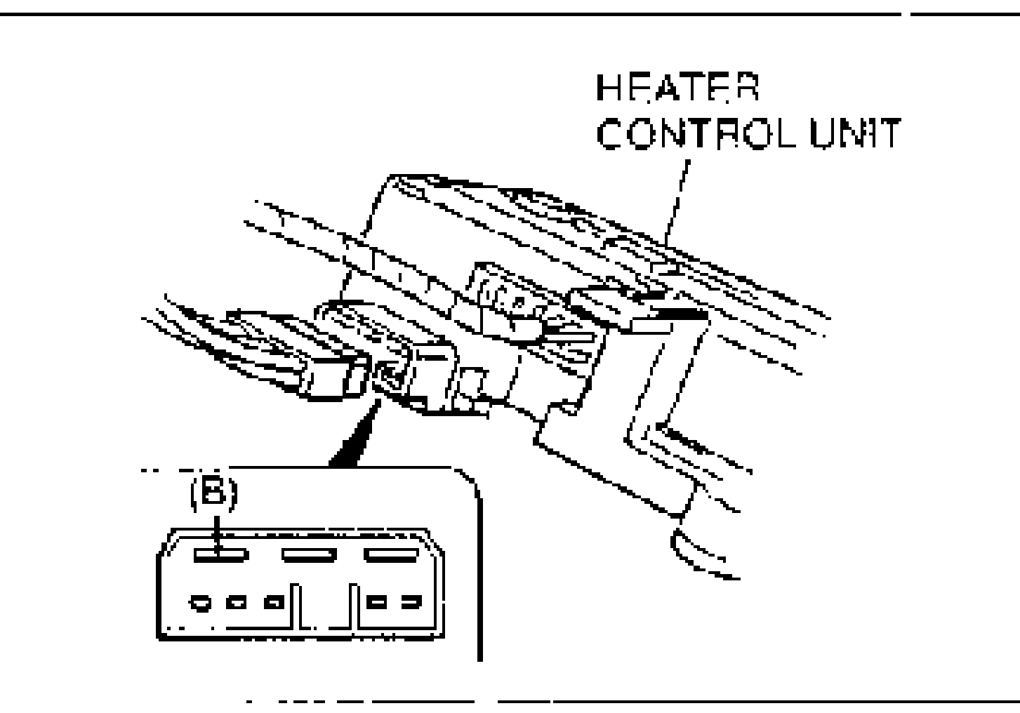
- 3Check for continuity between the (B) terminal wire of the fan switch connector and ground.
Step 7 — Fan switch (B) continuity to ground
Yes
ActionReplace fan switch (Refer to page G-44 or G-45)
No
ActionRepair wiring harness (Fan switch—GND)