
TROUBLESHOOTING
G-19prose procedureB6 vs K8 engine connector terminal layouts differ; voltage check branches per engine (L/B wire reconnect for B6, measure Y/B for K8).
Condenser fan / Action (Steps from jumper wire test)
(Y/B)
Condenser fanOperates (low speed)
ActionRemove jumper wire, reconnect ECM connector, and go to Step 6
(Y/B)
Condenser fanDoes not operate
ActionRemove jumper wire and go to Step 5
(P/B)
Condenser fanOperates (high speed)
ActionRemove jumper wire, reconnect ECM connector, and go to Step 6
(P/B)
Condenser fanDoes not operate
ActionRemove jumper wire and go to Step 5
Step 5
- 1Verify that the engine is running.
- 2Measure the voltage at the following terminal wires of the ECM connector.B+: Battery positive voltage
![Connector terminal layouts (two stacked views) for B6 and K8 engines, showing terminal positions for wires (L/B) [B6], (L/B) [K8], (Y/B), and (P/B).](/images/page-0811_fig2.png)
Wire / Voltage / Action (Step 5 voltage check)
(L/B)
VoltageB+
ActionReconnect ECM connector, and go to Step 6 [B6] or measure voltage at (Y/B) wire [K8]
(L/B)
VoltageOther
ActionRepair wiring harness (A/C relay—ECM)
(Y/B)
VoltageB+
ActionMeasure voltage at (P/B) wire
(Y/B)
VoltageOther
ActionRepair wiring harness (Condenser fan relay No.1—ECM)
(P/B)
VoltageB+
ActionGo to Step 6
(P/B)
VoltageOther
ActionRepair wiring harness (Condenser fan relay No.2—ECM)
Step 6
- 1Turn the ignition switch to OFF and disconnect the refrigerant pressure switch connector.
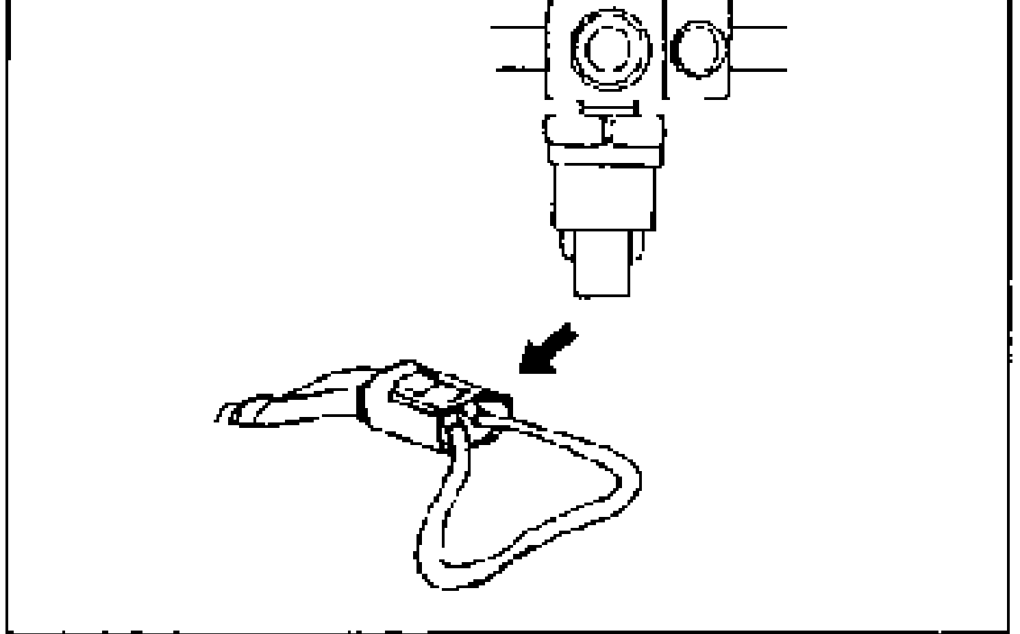
- 2Connect a jumper wire between terminals A and B of the refrigerant pressure switch connector.
- 3Start the engine.
- 4Turn the fan switch and A/C switch on and check the operation of the magnetic clutch and condenser fan.
Magnetic clutch, condenser fan / Action
Operate
ActionGo to Step 7
Do not operate
ActionRemove jumper wire, reconnect refrigerant pressure switch connector, and go to Step 8
Step 7
- 1Connect a manifold gauge set to the charging valves. (Refer to page G-50.)
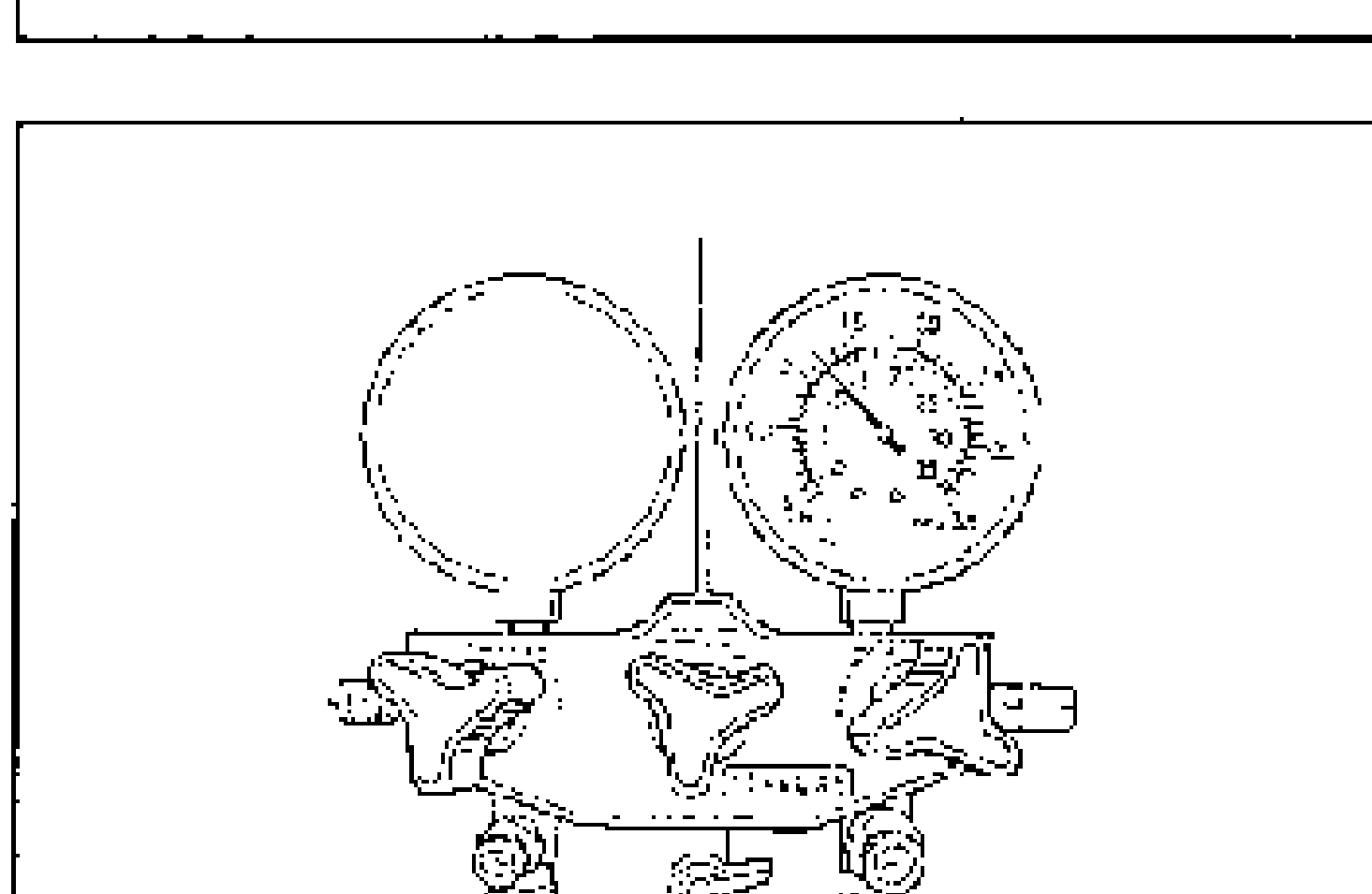
- 2Measure the high-pressure side pressure.
Refrigerant pressure / Action
0.21—2.9 MPa {2.1—30 kgf/cm2, 30—430 psi}
ActionReplace refrigerant pressure switch (Refer to page G-65)
Other
ActionCheck for leaks (Refer to page G-51)