
FLOWCHARTS — Flowchart No. 3 (continued): Steps 2–4
G-18flowchartSeparate A/C relay illustrations and AD FAN fuse locations for K8 (40A) and B6 (20A). [ ] values refer to the B6 engine. ECM connector shown is for B6.
TROUBLESHOOTING
Step 2
- 1Turn the ignition switch to ON.
- 2Measure the voltage at the following terminal wires of the A/C relay connector.B+: Battery positive voltage
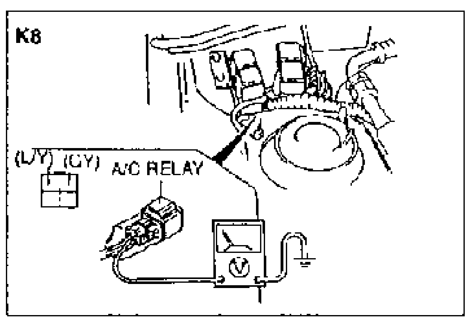
Step 2 — A/C relay connector voltage
(L/Y)
VoltageB+
ActionMeasure voltage at (GY) wire
(L/Y)
VoltageOther
ActionRepair wiring harness (AD FAN 40A [K8], AD FAN 20A [B6] fuse—A/C relay)
(GY)
VoltageB+
ActionGo to Step 3
(GY)
VoltageOther
ActionRepair wiring harness (REAR WIPER 10A fuse—A/C relay)
Step 3
- 1Turn the ignition switch to OFF.
- 2Remove the A/C relay.
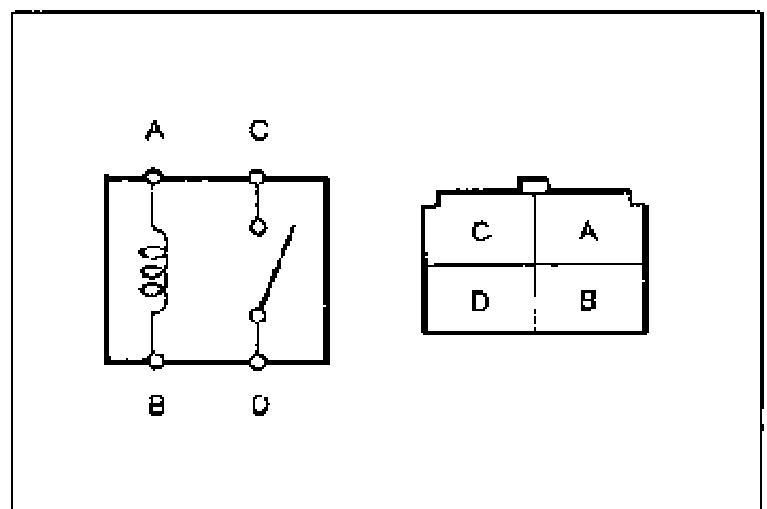
- 3Connect battery positive voltage and check for continuity between the terminals of the A/C relay.B+: Battery positive voltage
- 4If correct, reinstall the A/C relay and go to Step 4.
- 5If not as specified, replace the A/C relay.
Step 3 — A/C relay continuity
—
Connection GND—
Terminal A○
Terminal B○
Terminal C
Terminal D
A
Connection GNDB
Terminal A
Terminal B
Terminal C○
Terminal D○ (continuity C—D)
NOTE
○—○ : Continuity
Step 4
- 1Disconnect the ECM connector.
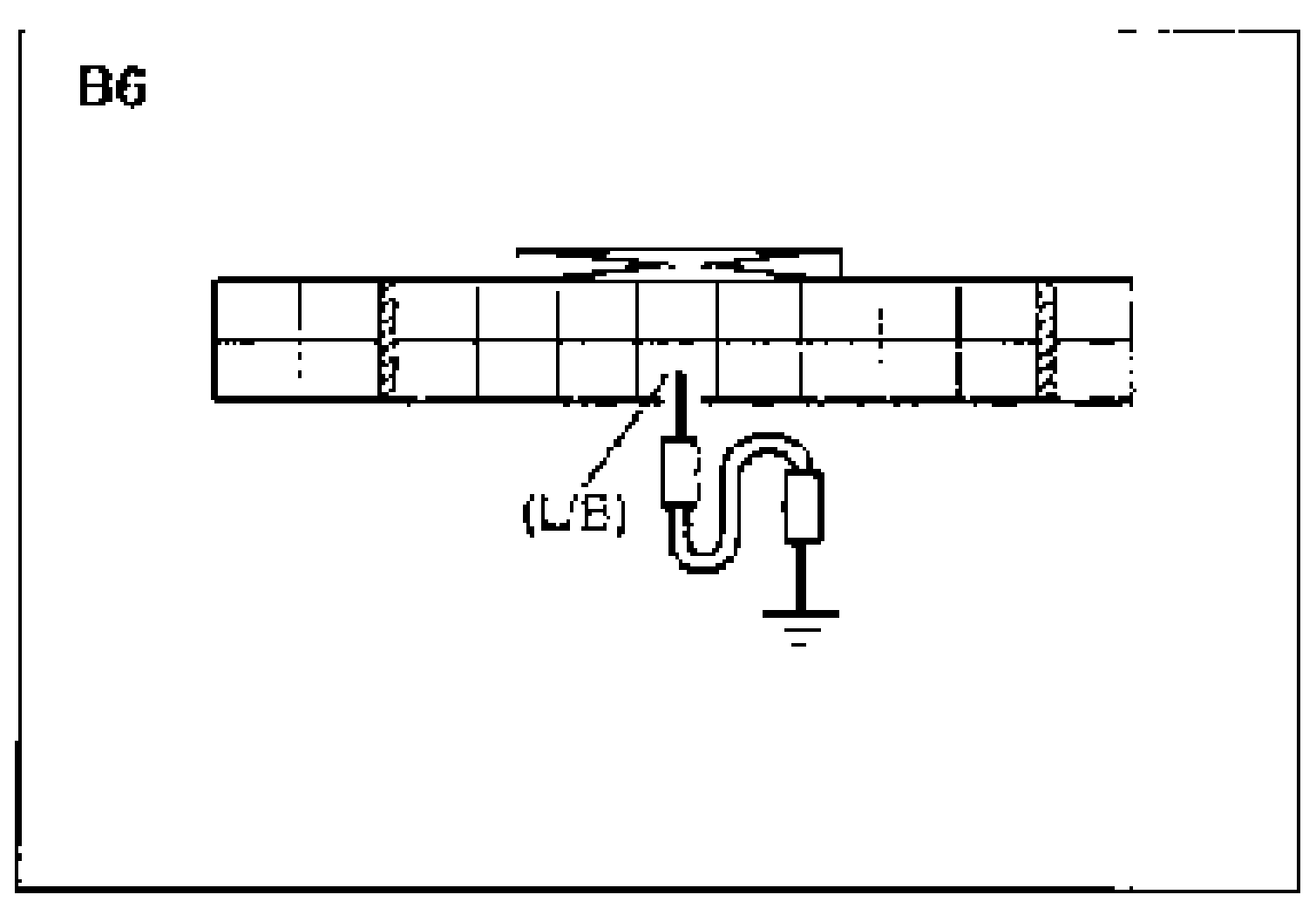
- 2Connect a jumper wire between the terminal wires of the ECM connector and ground.
- 3Start the engine and verify that the magnetic clutch and condenser fan operate.
Step 4 — ECM jumper test
(L/B)
Magnetic clutch, condenser fanOperate
ActionRemove jumper wire, reconnect ECM connector, and go to Step 6
(L/B)
Magnetic clutch, condenser fanDo not operate
ActionRemove jumper wire and go to Step 5