
TROUBLESHOOTING - Flowchart No. 13: Airflow is not cool; magnetic clutch and condenser fan operate
G-34flowchartStep 6 distinguishes logic type (REC/FRESH switch, mode switch) from wire type (REC/FRESH lever, mode lever).
Flowchart No. 13
Flowchart No.
Value13
Symptom
ValueAirflow is not cool; magnetic clutch and condenser fan operate
Related components
ValueRefrigerant system
Step 1
- 1Install the manifold gauge set. (Refer to page G-50.)
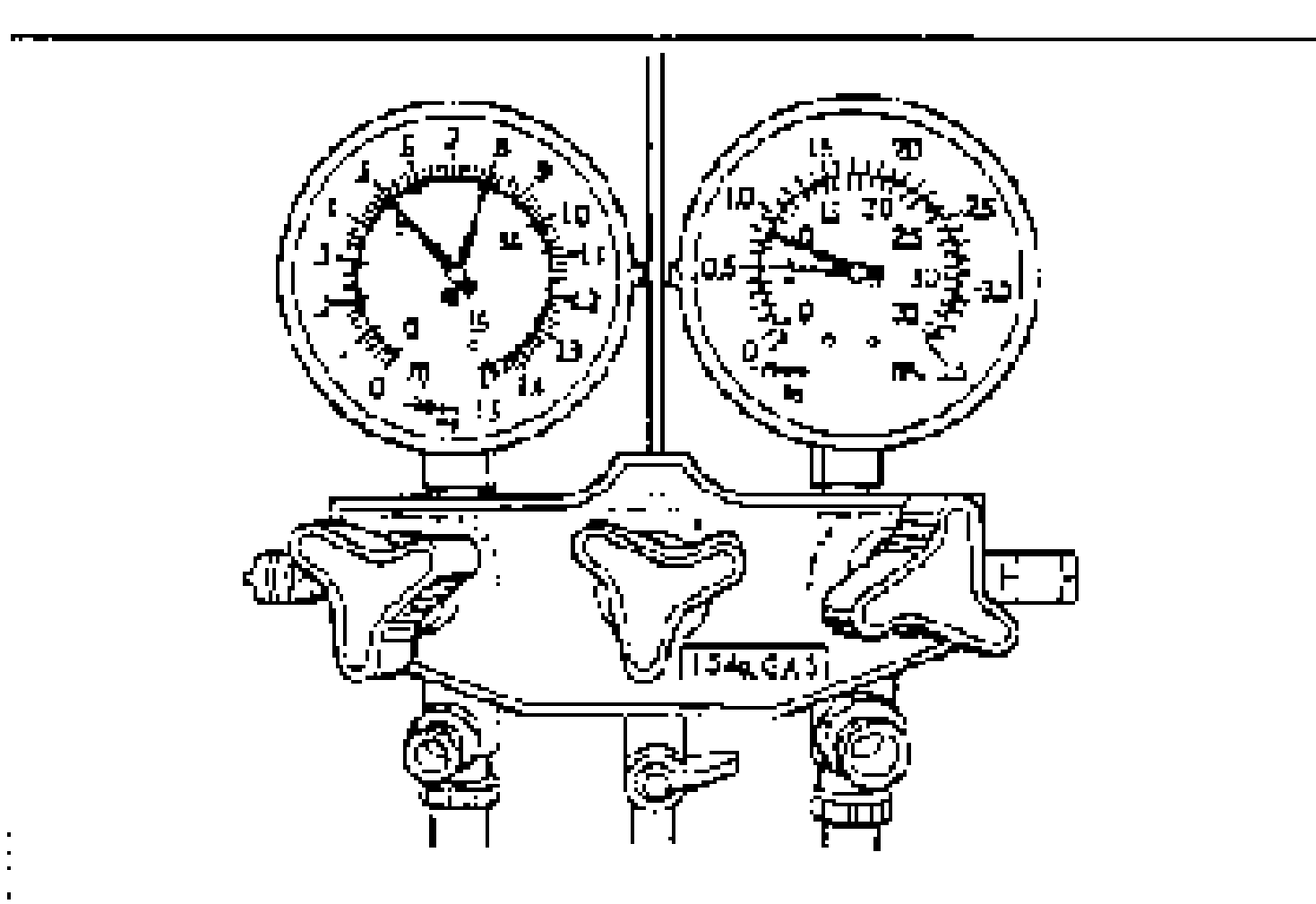
- 2Check the refrigerant pressure reading with the engine stopped.
- 3Verify that the high- and low-pressure-side readings of the manifold gauge are at 493-788 kPa {5.02-8.04 kgf/cm2, 72-114 psi}. If the pressure readings are lower than specified, recharge the refrigerant amount. (Refer to page G-50.) If the pressure readings are within specification but there is insufficient cooling, go to the next step. If the pressure readings are within specification and there are no leaks, the refrigerant amount is OK.
- 4Start the engine and run it at a constant 2,000 rpm.
- 5Turn the A/C switch on, set the fan switch at MAX-HI, and set the air intake mode at recirculate.
- 6If the A/C compressor is short-cycling, note the low-pressure-side reading at which the magnetic clutch kicks out.
- 7If the pressure is 170 kPa {1.7 kgf/cm2, 24 psi} or lower, evacuate and recharge the refrigerant system with the proper amount of refrigerant. (Refer to page G-50.) If the pressure is 210 kPa {2.1 kgf/cm2, 30 psi} or higher, inspect the thermoswitch. (Refer to page G-69.)
Step 2
- 1Install the manifold gauge set. (Refer to page G-50.)
- 2Shut all doors and windows.
- 3Warm up the engine and run it at a constant 1,500 rpm.
- 4Set the fan switch to the fourth position.
- 5Turn the A/C switch on.
- 6Set the REC/FRESH switch (logic type) or REC/FRESH lever (wire type) at recirculate.
- 7Set the mode switch (logic type) or mode lever (wire type) at VENT.
- 8Set the temperature control lever at MAX COLD.
- 9Measure the ambient temperature and the high- and low-pressure-side readings of the manifold gauge.
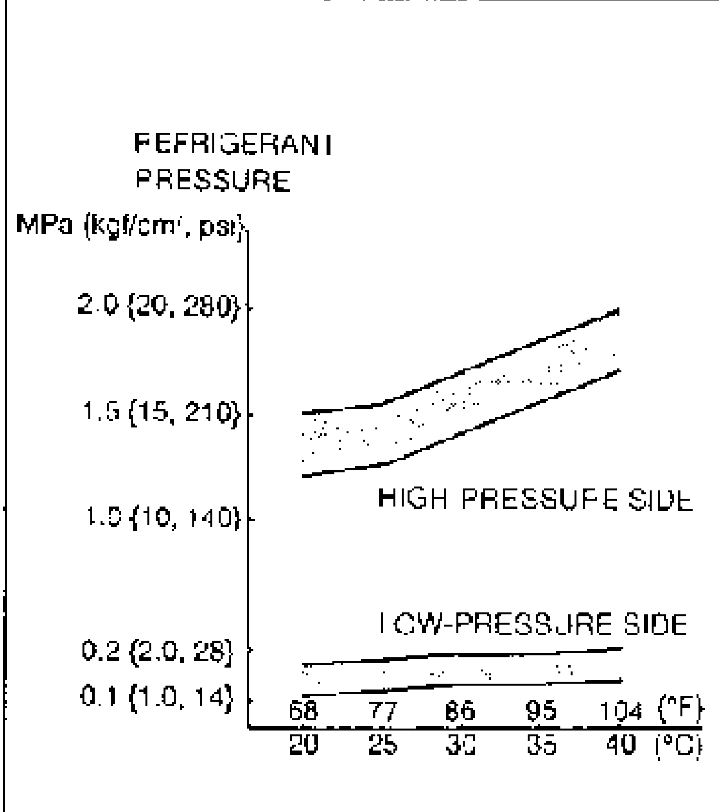
- 10If the high- and low-pressure-side readings are in the shaded zones shown in the figure, the refrigerant system is normal.
- 11If not as specified, refer to "Refrigerant pressure flowchart" and repair the air conditioning system. (Refer to page G-35.)