
TROUBLESHOOTING
G-20prose procedureK8 and B6 engines have different voltage thresholds for the Step 8 heater control unit (G) terminal check (K8: 1.5—3.5 / 4.5—5.5; B6: Below 2.5 / B+).
Step 8
- 1Verify that the ignition switch and fan switch are on.
- 2Measure the voltage at the (G) terminal wire of the heater control unit connector.B+: Battery positive voltage
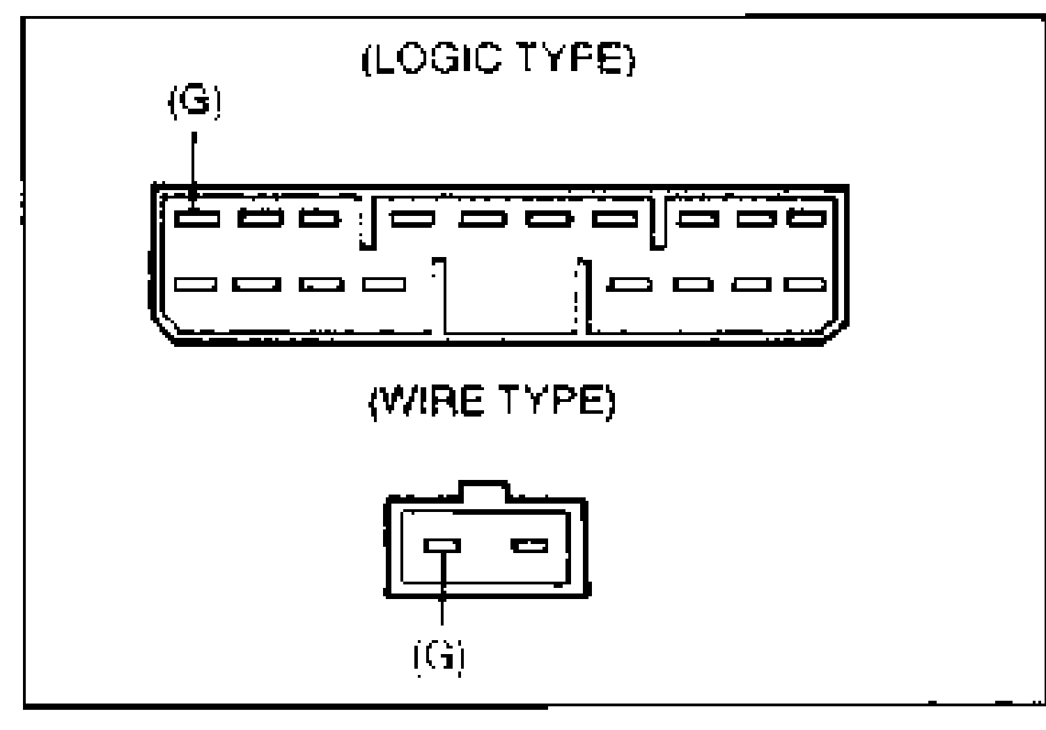
Engine / A/C switch / Voltage / Action (Step 8)
K8
A/C switchON
Voltage (V)1.5—3.5
ActionMeasure voltage with A/C switch off
K8
A/C switchON
Voltage (V)Other
ActionGo to Step 10
K8
A/C switchOFF
Voltage (V)4.5—5.5
ActionGo to Step 9
K8
A/C switchOFF
Voltage (V)Other
ActionGo to Step 10
B6
A/C switchON
Voltage (V)Below 2.5
ActionMeasure voltage with A/C switch off
B6
A/C switchON
Voltage (V)Other
ActionGo to Step 10
B6
A/C switchOFF
Voltage (V)B+
ActionGo to Step 9
B6
A/C switchOFF
Voltage (V)Other
ActionGo to Step 10
Step 9
- 1Measure the voltage at the (GY) terminal wire of the heater control unit connector.B+: Battery positive voltage
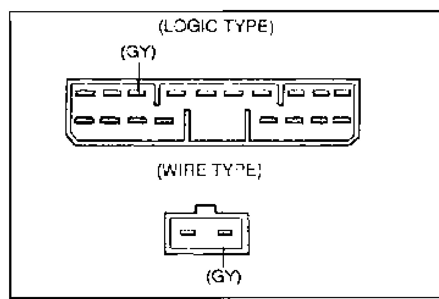
Voltage / Action (Step 9)
B+
ActionReplace heater control unit (Refer to page G-43)
Other
ActionRepair wiring harness (REAR WIPER 10A—Heater control unit)
Step 10
- 1Remove the glove compartment and glove compartment cover. (Refer to the 1995 MX-3 Workshop Manual, section S.)
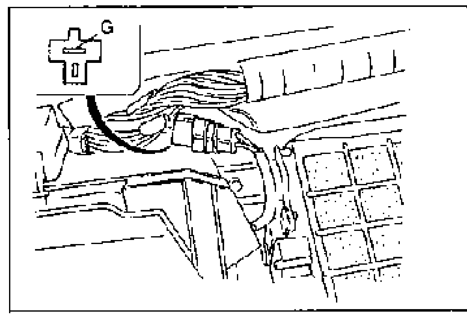
- 2Measure the voltage at the (G) terminal wire of the thermoswitch connector.B+: Battery positive voltage
Voltage / Action (Step 10)
B+
ActionGo to Step 11
Other
ActionRepair wiring harness (Thermoswitch—Heater control unit)
Step 11
- 1Measure the voltage at the (B/R) terminal wire of the refrigerant pressure switch connector.B+: Battery positive voltage
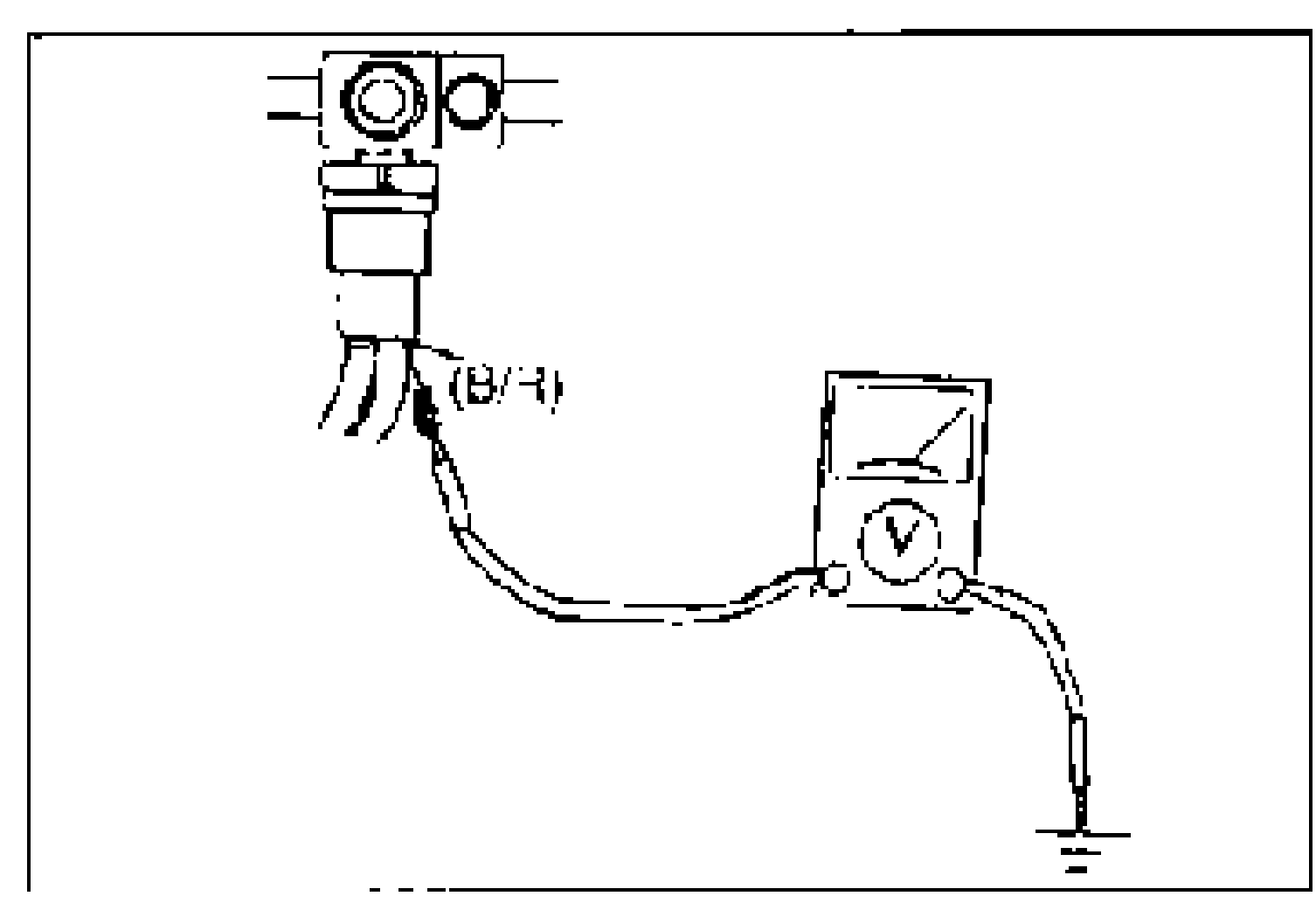
Voltage / Action (Step 11)
B+
ActionGo to Step 13
Other
ActionGo to Step 12
Step 12
- 1Disconnect the thermoswitch connector.
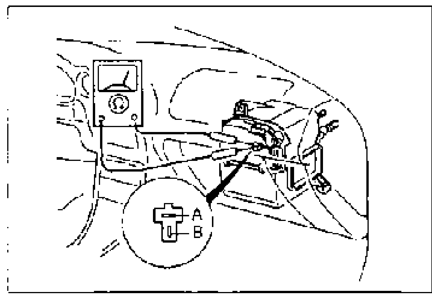
- 2Check for continuity between terminals A and B of the thermoswitch.
Continuity / Action (Step 12)
Yes
ActionRepair wiring harness (Refrigerant pressure switch—Thermoswitch)
No
ActionReplace thermoswitch (Refer to page G-68)