
AIR CONDITIONER — REFRIGERANT SYSTEM SERVICE PROCEDURES
G-50prose procedureREFRIGERANT SYSTEM SERVICE PROCEDURES
Manifold Gauge Set Installation
- 1Fully close the valves of the manifold gauge.
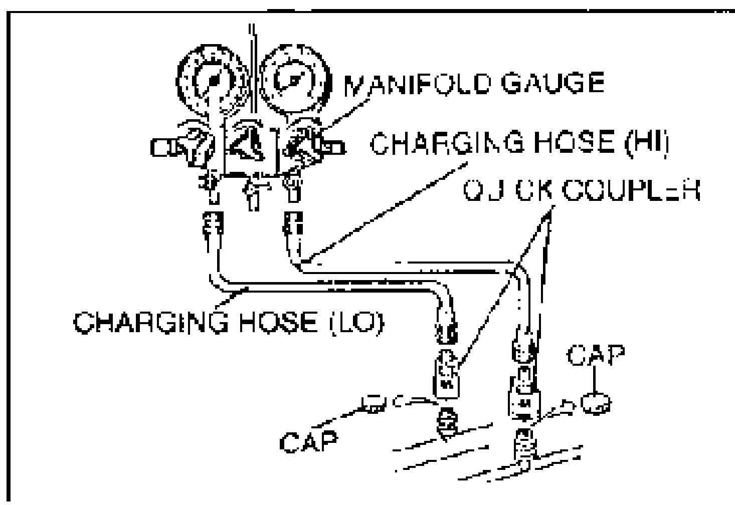
- 2Connect charging hoses to the high- and low-pressure side joints of the manifold gauge.
- 3Connect quick couplers to the ends of the charging hoses.
- 4Remove the caps from the charging valves of the high- and low-pressure side cooler pipes.
- 5Connect the quick couplers to the charging valves of the cooler pipes.
Charging
- 1Install the manifold gauge set.
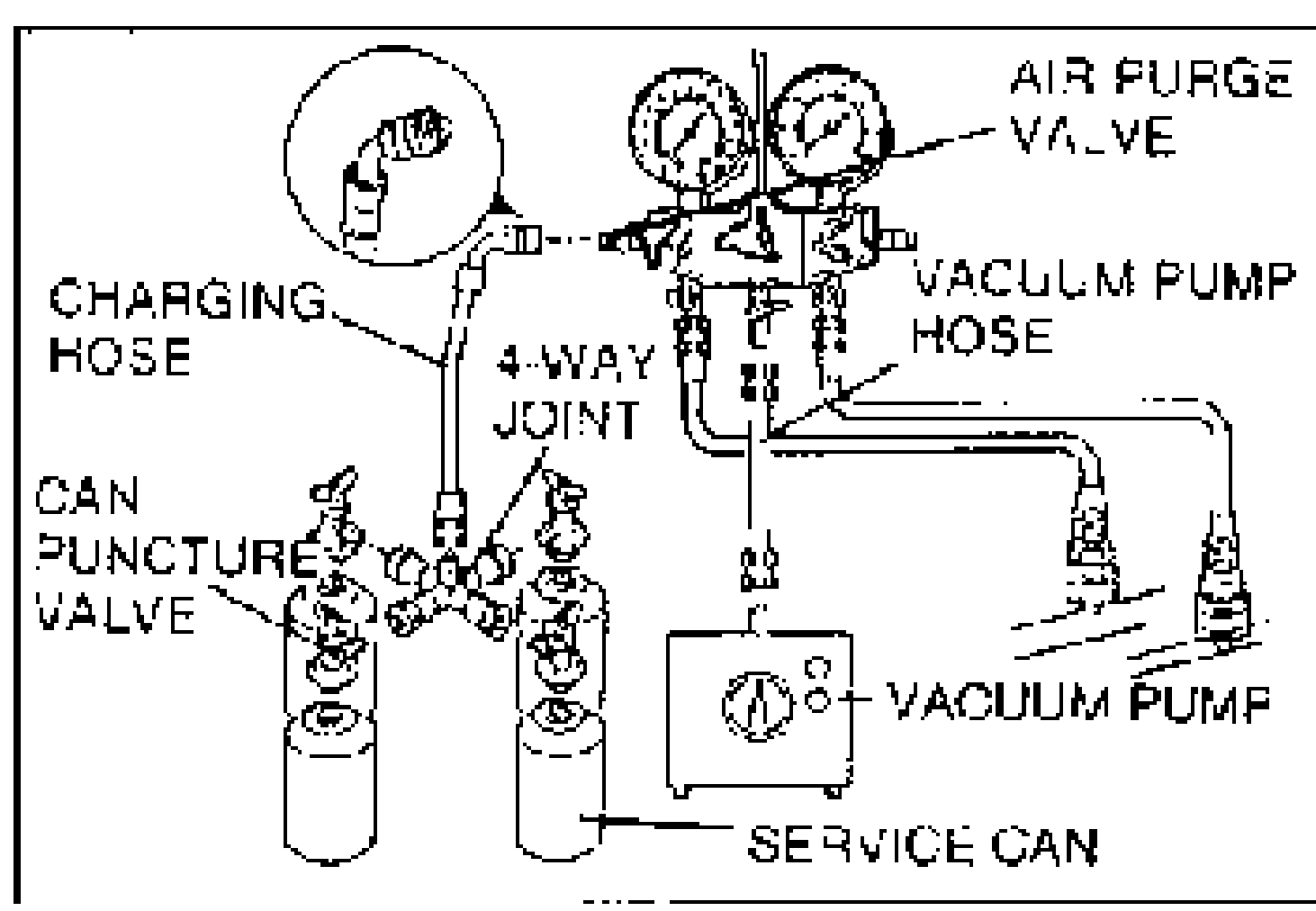
- 2Connect the tap pin side of the charging hose to the air purge valve of the manifold gauge.
- 3Connect the vacuum pump hose to the center joint of the manifold gauge.
- 4Connect the vacuum pump hose to the vacuum pump.
- 5Connect can puncture valves to a 4-way joint.
- 6Fully open the can puncture valves and connect service cans to the valves.Regular amount of refrigerant: 750g {26.5 oz}
- 7Fully close any can puncture valve that is not connected to a service can.
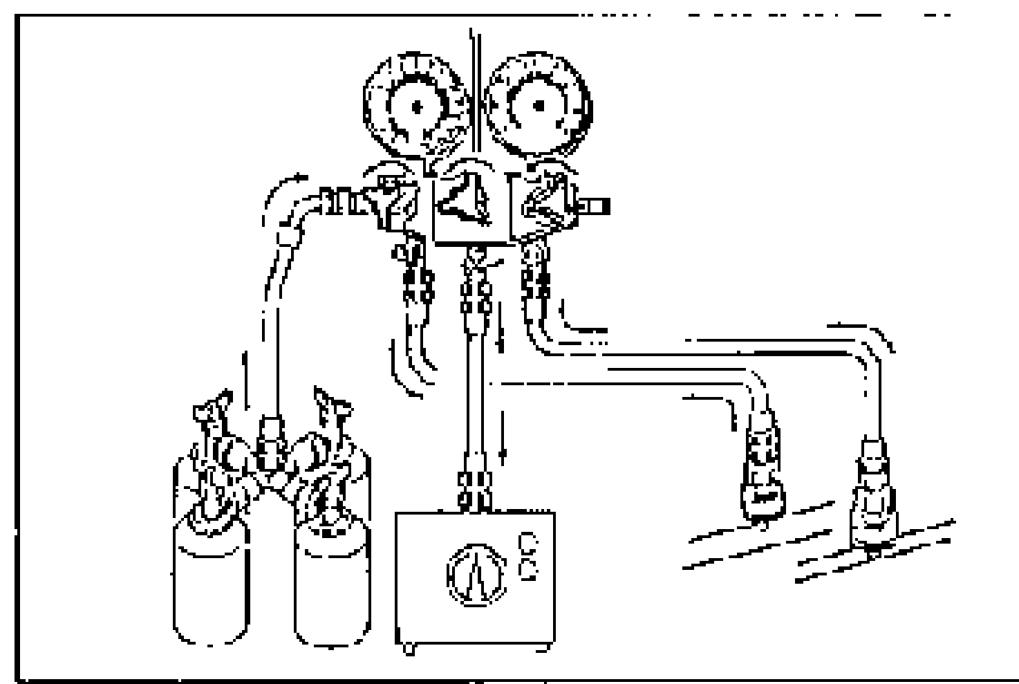
- 8Connect the 4-way joint to the charging hose that is connected to the gauge set air purge valve.
- 9Open all the valves of the manifold gauge.
- 10Start the vacuum pump and let it operate for 15 minutes.
- 11After 15 minutes, verify that the high- and low-pressure-side readings of the manifold gauge are at -101 kPa {-760 mmHg, -29.9 inHg}. Close each valve of the manifold gauge.
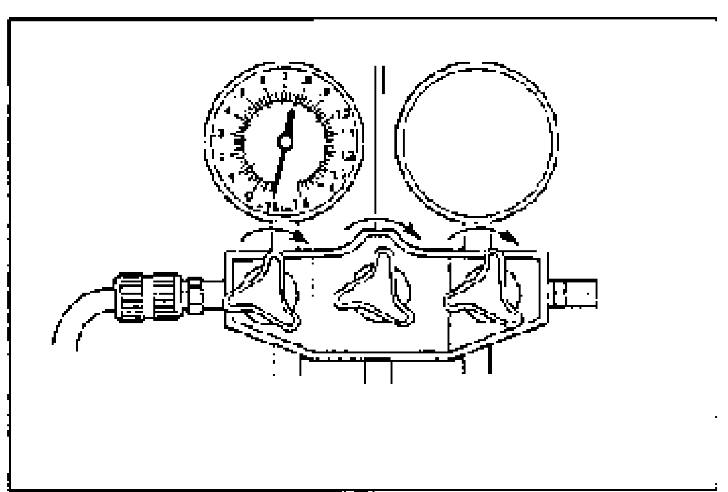
- 12Stop the vacuum pump and wait for about 5 minutes.
- 13After 5 minutes, check the low-pressure-side reading of the manifold gauge. If the reading has changed, check for leaks and then repeat from step 9. If reading has not changed, go to step 14.
- 14Open the service cans by using the can puncture valves.
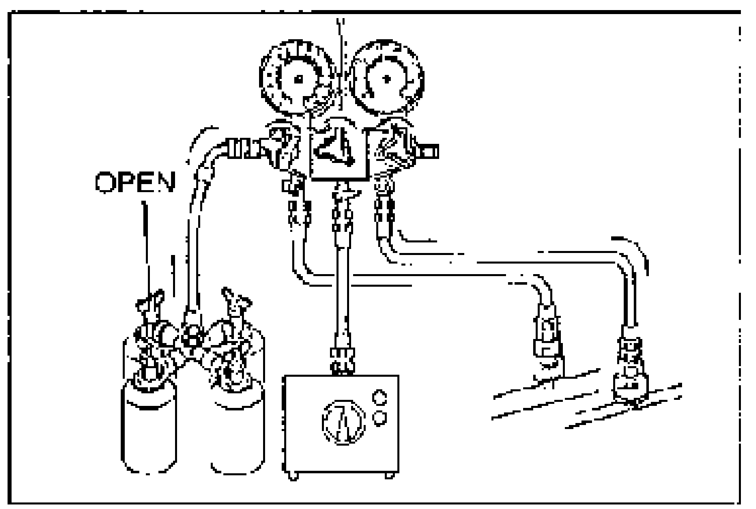
- 15Open the high-pressure side valve to the manifold gauge and charge with refrigerant until the low-pressure-side reading is at 100 kPa {1 kgf/cm2, 10 psi}.
| Specification | Value |
|---|---|
| Regular amount of refrigerant | 750g {26.5 oz} |
Regular amount of refrigerant
750g {26.5 oz}