
AIR CONDITIONER — Performance Test
G-52prose procedureREC/FRESH and mode controls differ between wire type and logic type A/C control panels.
Performance Test
After servicing the refrigerant system, test its performance.
Performance Test
- 1Install the manifold gauge set. (Refer to page G-50.)
- 2Place a dry-bulb thermometer in the center ventilator outlet.
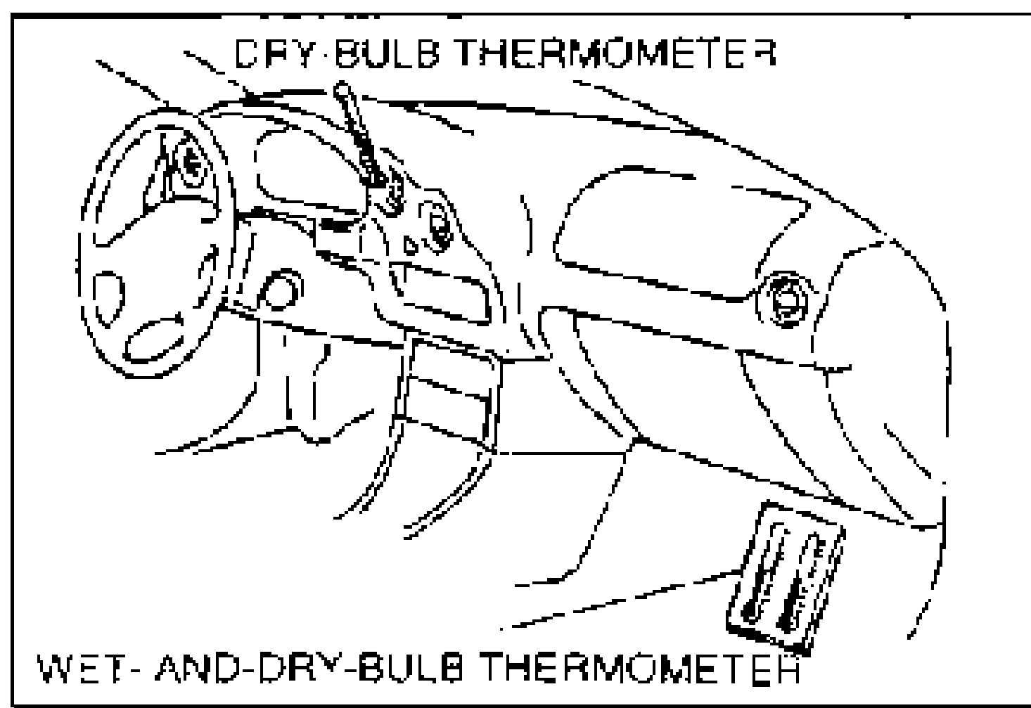
- 3Place a wet-and-dry-bulb thermometer at the blower inlet.
- 4Open all doors and windows.
- 5Warm up the engine and run it at constant 1,500 rpm.
- 6Set the fan switch at the fourth position.
- 7Turn the A/C switch on.
- 8Set the REC/FRESH lever (wire type) or REC/FRESH switch (logic type) at recirculate.
- 9Set the mode lever (wire type) or mode switch (logic type) to VENT.
- 10Set the temperature control lever to MAX COLD.
- 11Wait until the air conditioner output temperature stabilizes.Stabilized condition — Blower inlet temperature: 25-35 degC {77-95 degF}; High-pressure-side reading: 1380-1660 kPa {14.0-17.0 kgf/cm2, 200-241 psi}
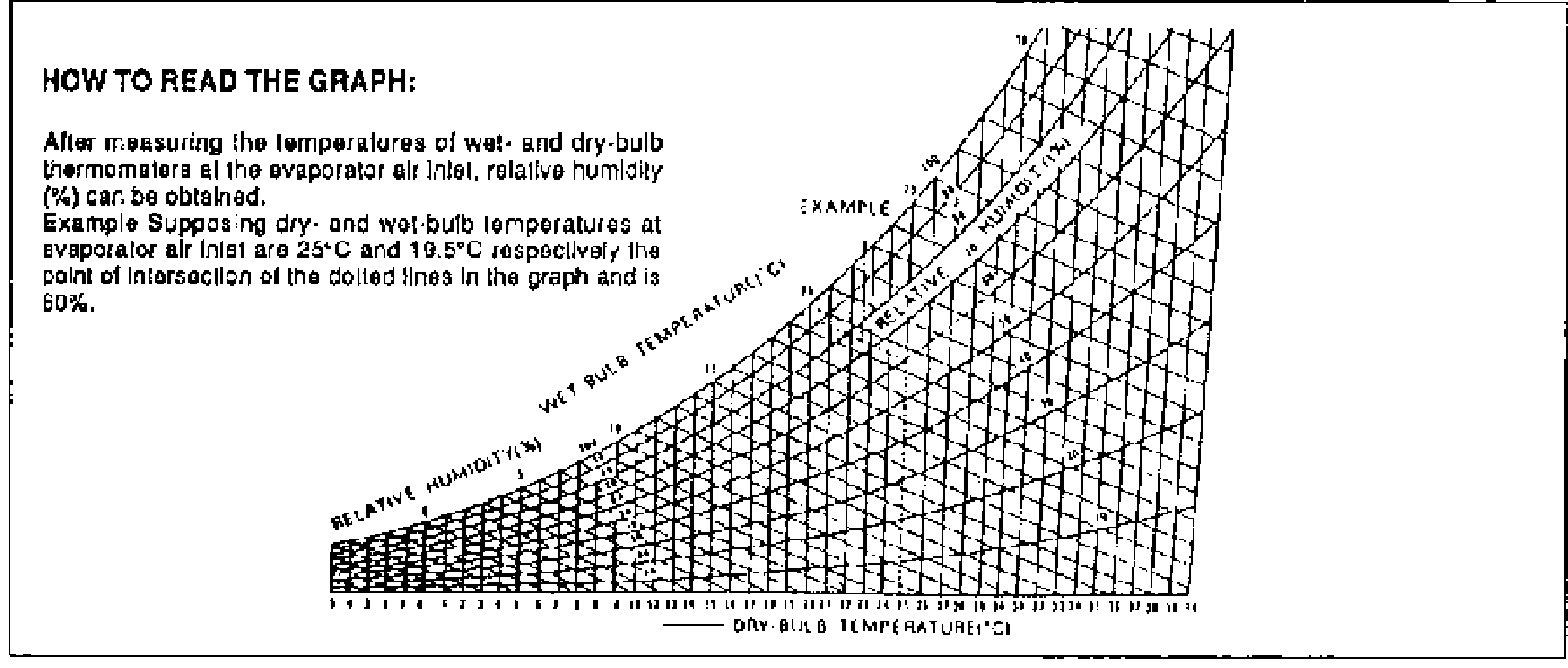
- 12After the air conditioner stabilizes, read the wet-and-dry-bulb thermometer, and then calculate the relative humidity by using the graph below.
- 13Read the dry thermometer at the air outlet, and calculate the difference between the inlet dry-bulb and outlet dry-bulb temperatures.
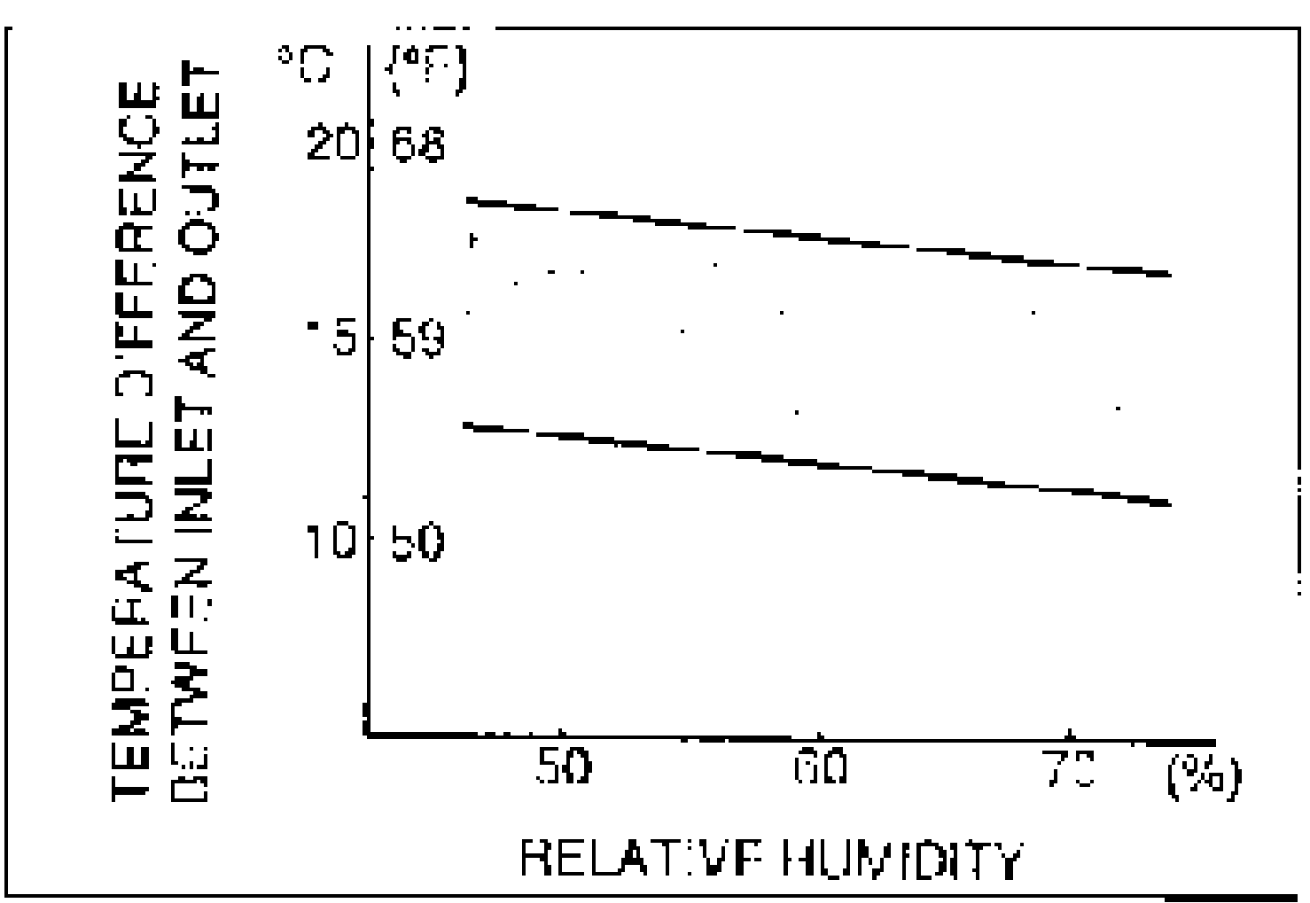
- 14Verify that the intersection of the relative humidity and temperature difference is in the shaded zone.
| Specification | Value |
|---|---|
| Blower inlet temperature | 25-35degC {77-95 degF} |
| High-pressure-side reading | 1380-1660kPa {14.0-17.0 kgf/cm2, 200-241 psi} |
Blower inlet temperature
25-35degC {77-95 degF}
High-pressure-side reading
1380-1660kPa {14.0-17.0 kgf/cm2, 200-241 psi}