
TROUBLESHOOTING - Flowchart No. 9: Airflow mode does not change (wire type)
G-29flowchartStep 4
- 1Verify that the ignition switch is at OFF.
- 2Disconnect the heater control unit connector.
- 3Check for continuity between the terminal wires of the airflow mode actuator and heater control unit connectors.
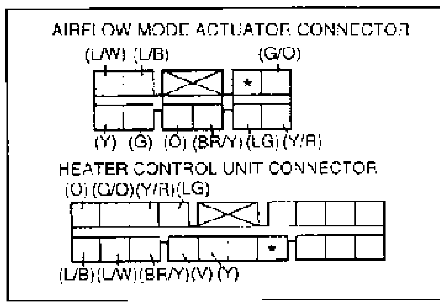
Step 4 - Continuity check
(L/W) (L/B) (O) (G/O) (Y/R) (LG) (BR/Y) (Y) (G)-(V)
ContinuityYes (all)
ActionCheck heater control unit (Refer to page G-46)
(L/W) (L/B) (O) (G/O) (Y/R) (LG) (BR/Y) (Y) (G)-(V)
ContinuityNo (portion)
ActionRepair faulty wiring harness
Flowchart No. 9
Flowchart No.
Value9
Symptom
ValueAirflow mode does not change (wire type)
Related components
ValueAirflow mode wire, mode door assembly, mode lever
Step 1
- 1Verify that the airflow mode wire is secured to the mode door link and that the outer tube is secured by the clip.
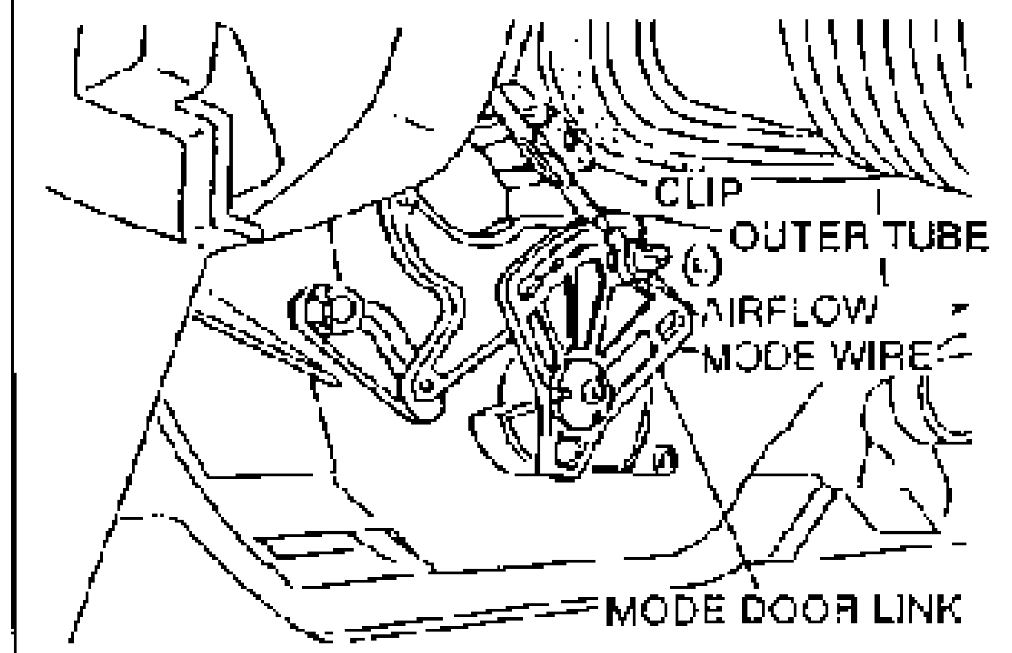
Step 1
Secured
ActionGo to Step 2
Not secured
ActionConnect airflow mode wire and/or outer tube (Refer to page G-47)
Step 2
- 1Turn the ignition switch to ON and set the fan switch to the fourth position.
- 2Move the mode lever from VENT to DEF and verify that the mode door link operates and the air outlets change.
Step 2
Mode door link does not operate
ActionCheck connection between mode door and airflow mode wire (Refer to page G-47)
Lever sticks, air outlets change
ActionCheck wire routing from mode door to mode door link. Check lubrication of lever (Refer to page G-47)
Air outlets do not change; mode door link operates
ActionCheck mode door for damage (Refer to page G-38)
Air outlets and lever indication do not match
ActionAdjust outer tube and mounting (Refer to page G-47)