
AIR CONDITIONER — Receiver/Drier and Refrigerant Pressure Switch
G-65prose procedureUnverifiedRECEIVER/DRIER
Removal / Installation
- 1Discharge the refrigerant from the system.
- 2Remove the airflow meter.
- 3Remove the coolant reservoir.
- 4Disconnect the cooler pipes from the receiver/drier.
- 5Remove the receiver/drier from the bracket.
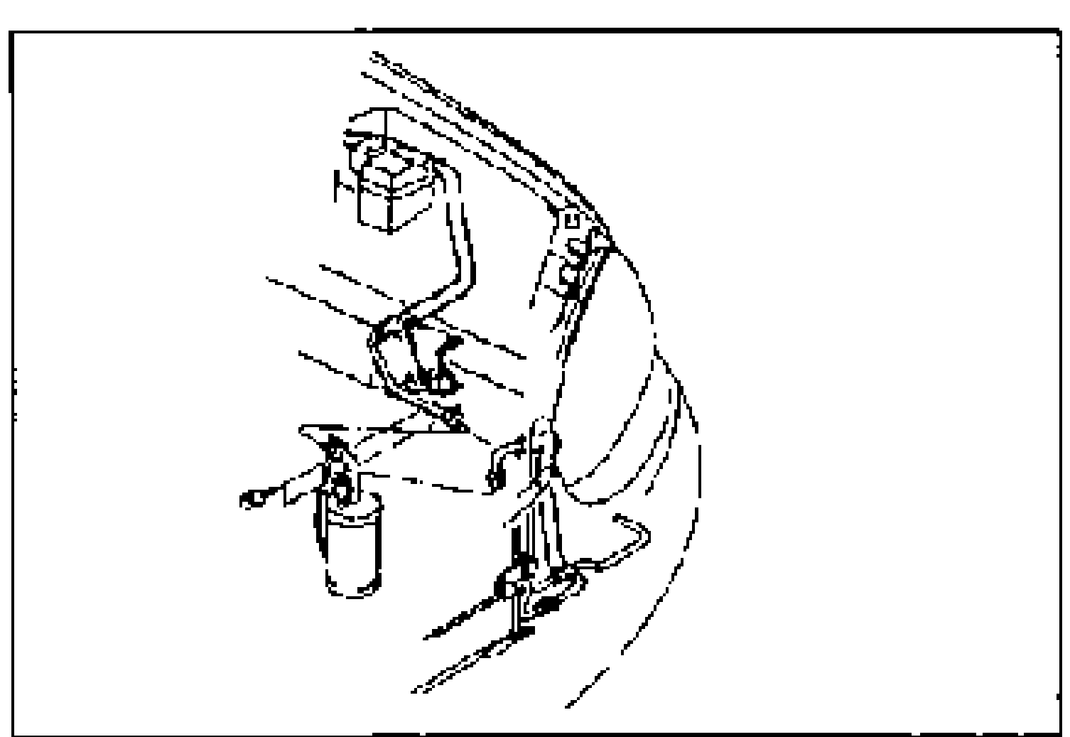
- 6Install in the reverse order of removal. Apply clean compressor oil to the O-rings before connecting the fittings. When installing a new receiver/drier, add 10 ml {10 cc, 0.3 fl oz} compressor oil through the high-pressure side of the A/C compressor.
| Specification | Value |
|---|---|
| Receiver/drier inlet | 10—19N·m {1.0—2.0 kgf·m, 8—14 ft·lbf} |
| Receiver/drier outlet | 15—24N·m {1.5—2.5 kgf·m, 11—18 ft·lbf} |
Receiver/drier inlet
10—19N·m {1.0—2.0 kgf·m, 8—14 ft·lbf}
Receiver/drier outlet
15—24N·m {1.5—2.5 kgf·m, 11—18 ft·lbf}
REFRIGERANT PRESSURE SWITCH
Removal / Installation
- 1Discharge the refrigerant from the system.
- 2Disconnect the refrigerant pressure switch connector and remove the refrigerant pressure switch.
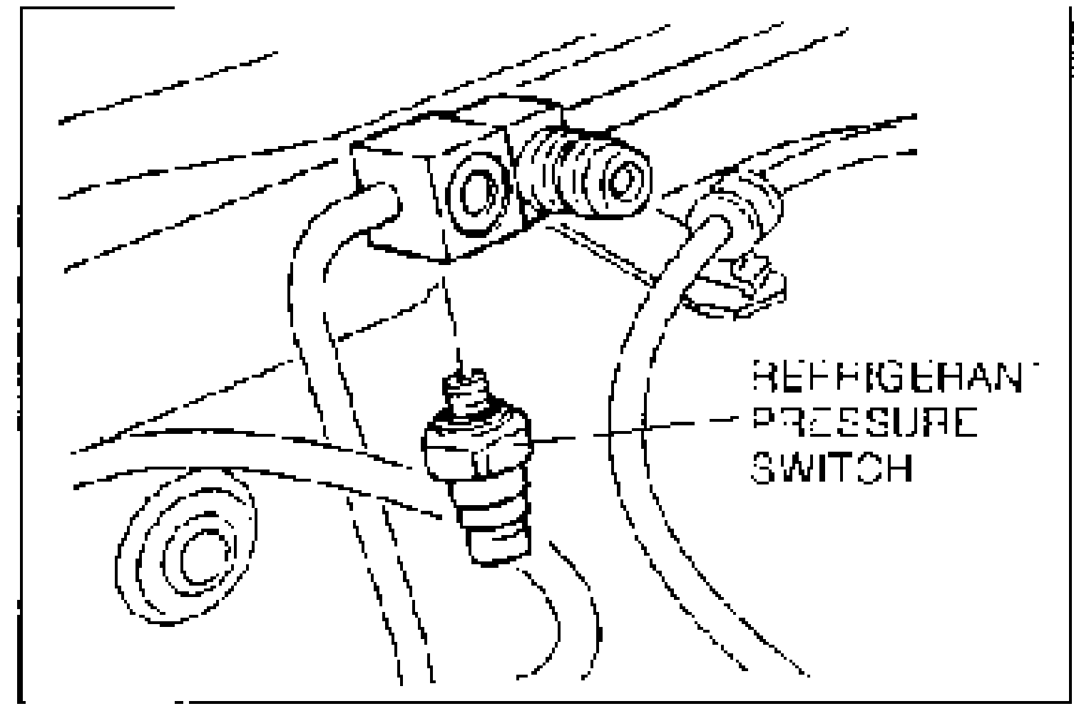
- 3Before installing the refrigerant pressure switch, wrap sealing tape on the threads of the switch and replace the O-ring. Then install in the reverse order of removal.
| Specification | Value |
|---|---|
| refrigerant pressure switch | ≈96N·m |
refrigerant pressure switch
96N·m
Inspection
If problems occur in the refrigerant system that cause abnormally high pressure or abnormally low pressure, the refrigerant pressure switch will cut power to the magnetic clutch to protect the mechanical components. If the pressure recovers to within normal operating range, the power will be restored. These operating values are shown in the figure.
Inspection
- 1Turn the ignition switch to OFF.
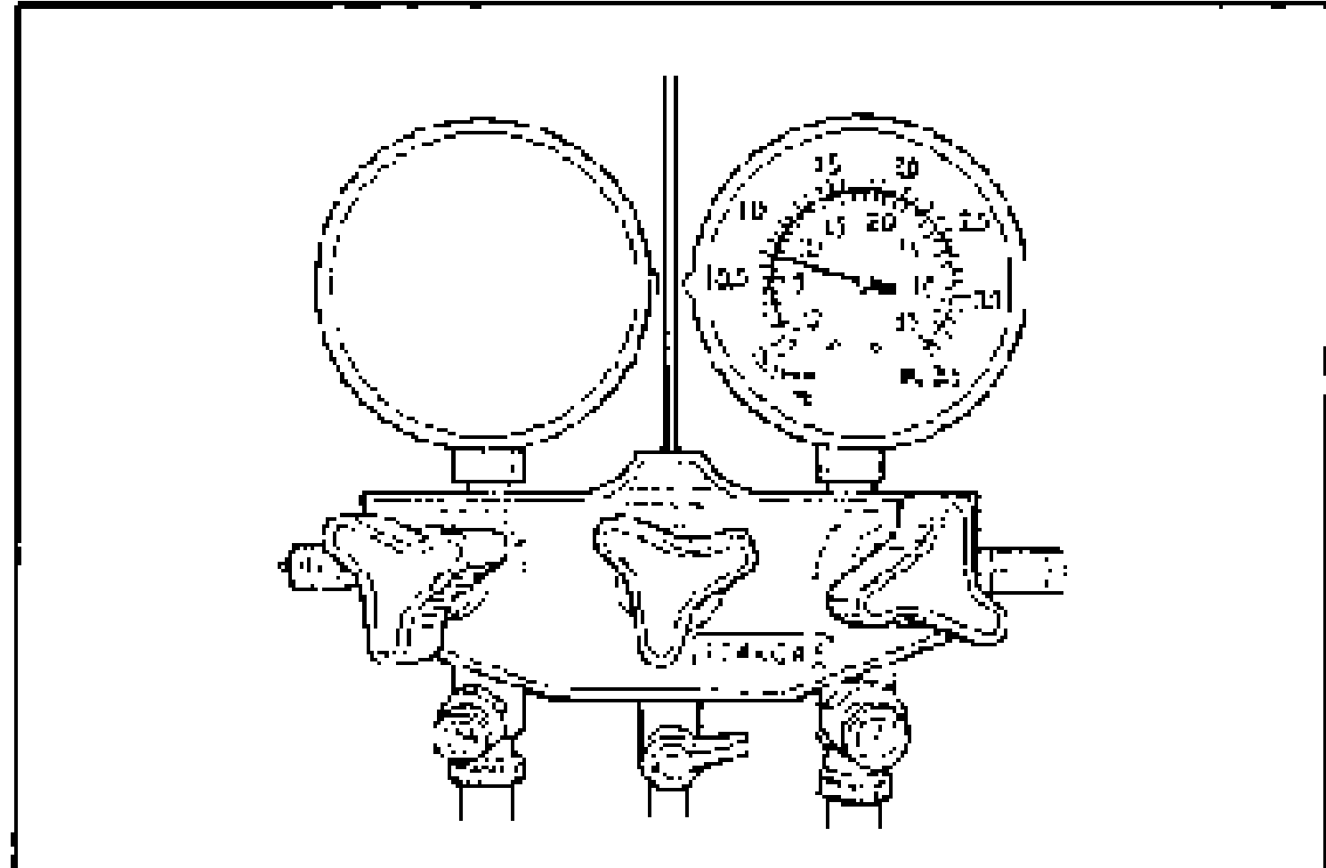
- 2Connect the manifold gauge set and measure the high-pressure-side reading. (Refer to page G-50.)
- 3If not as specified, refer to page G-53 and check the refrigerant system.
| Specification | Value |
|---|---|
| High-pressure-side reading | Above 450kPa {4.6 kgf·cm², 65 psi} |
High-pressure-side reading
Above 450kPa {4.6 kgf·cm², 65 psi}