
TROUBLESHOOTING
G-28prose procedureStep 1
- 1Disconnect the connecting rod from the mode main link.
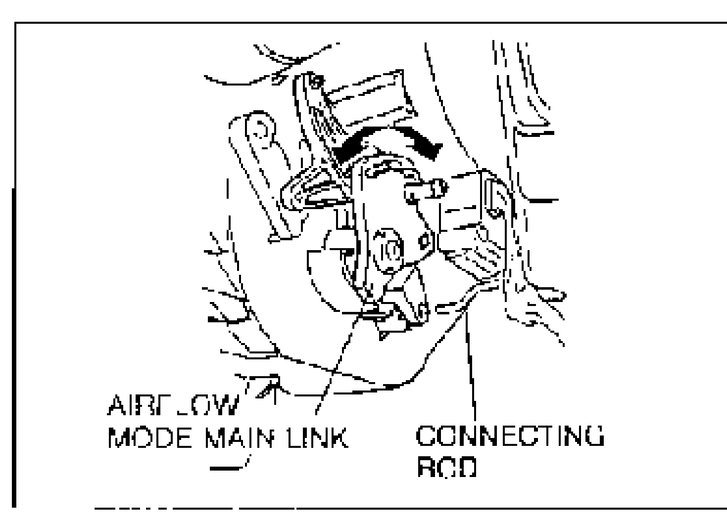
- 2Turn the ignition switch to ON and set the fan switch to the fourth position.
- 3Check the outlet airflow while handling the airflow mode main link.
Outlet airflow / Action (Step 1)
Normal
ActionGo to Step 2
Abnormal
ActionCheck heater unit (Refer to page G-38)
Step 2
- 1Turn the ignition switch to OFF.
- 2Disconnect the airflow mode actuator connector.
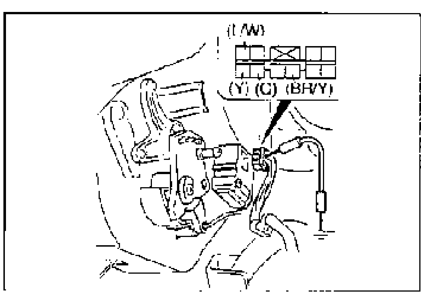
- 3Connect a jumper wire between the (L/W) and (BR/Y) terminal wires of the airflow mode actuator connector and ground.
- 4Turn the ignition switch to ON.
- 5Measure the voltage at the following terminal wires of the airflow mode actuator connector.B+: Battery positive voltage
Wire / GND / Voltage / Action (Step 2)
(G)
GND(L/W)
VoltageB+
ActionMeasure voltage at (Y) wire
(G)
GND(L/W)
VoltageOther
ActionGo to Step 4
(Y)
GND(BR/Y)
VoltageB+
ActionGo to Step 3
(Y)
GND(BR/Y)
VoltageOther
ActionGo to Step 4
Step 3
- 1Turn the ignition switch to OFF.
- 2Check for continuity between the following terminal wires of the airflow mode actuator connector and ground while turning the mode switches on.
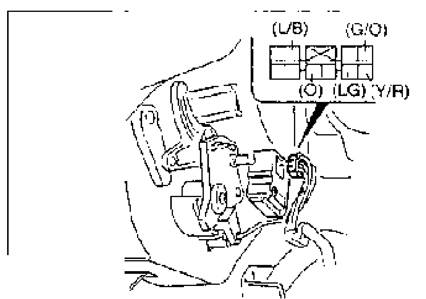
Wire / Mode switch / Continuity / Action (Step 3)
(L/B)
Mode switchVENT
ContinuityYes
ActionCheck for continuity at (O) wire
(L/B)
Mode switchVENT
ContinuityNo
ActionGo to Step 4
(O)
Mode switchB/L
ContinuityYes
ActionCheck for continuity at (G/O) wire
(O)
Mode switchB/L
ContinuityNo
ActionGo to Step 4
(G/O)
Mode switchHEAT
ContinuityYes
ActionCheck for continuity at (Y/R) wire
(G/O)
Mode switchHEAT
ContinuityNo
ActionGo to Step 4
(Y/R)
Mode switchH/D
ContinuityYes
ActionCheck for continuity at (LG) wire
(Y/R)
Mode switchH/D
ContinuityNo
ActionGo to Step 4
(LG)
Mode switchDEF
ContinuityYes
ActionReplace airflow mode actuator (Refer to page G-38)
(LG)
Mode switchDEF
ContinuityNo
ActionGo to Step 4