
TROUBLESHOOTING
G-21wiring diagramA/D FAN fuse rating differs by engine: 40A for K8, 20A for B6. K8 uses two condenser fan relays (No.1, No.2); B6 uses a single condenser fan relay.
Step 13
- 1Measure the voltage at the (BR) terminal wire of the ECM connector.B+: Battery positive voltage
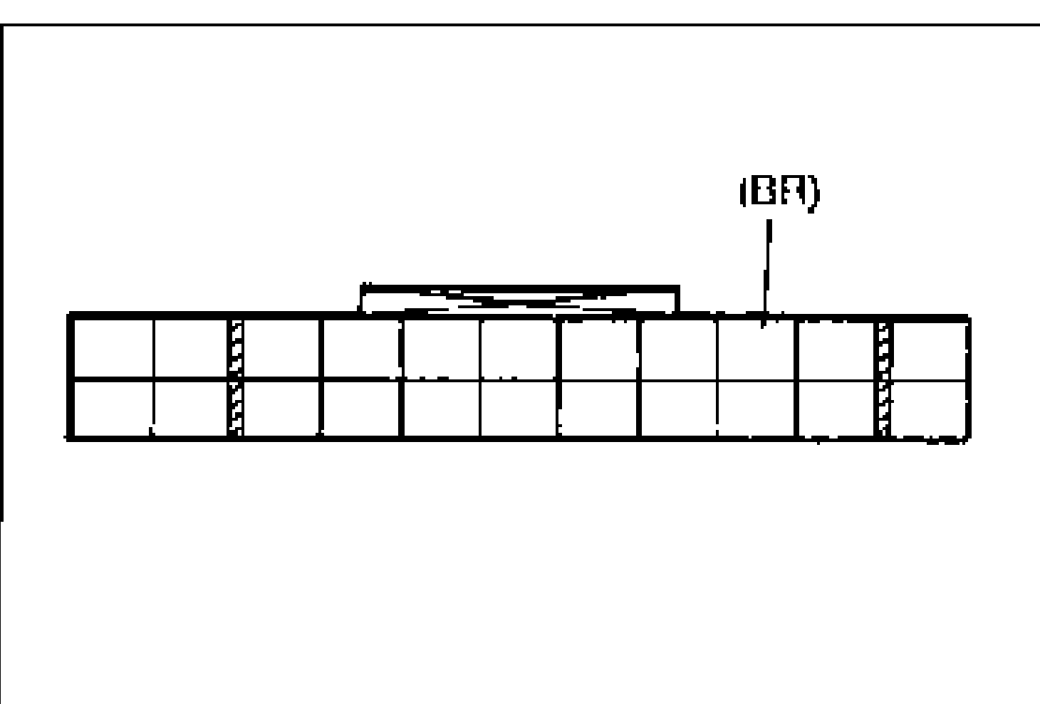
Voltage / Action (Step 13)
B+
ActionCheck ECM (Refer to 1995 MX-3 Workshop Manual, sections F1 and F2)
Other
ActionRepair wiring harness (ECM—Refrigerant pressure switch)
Flowchart No. 4
4
DetailSymptom: Magnetic clutch does not operate, but condenser fan operates normally
4
DetailRelated components: Magnetic clutch, wiring harness
Air conditioning / condenser fan control circuit
Components (13)
A/D FAN fuse 40A [K8] / 20A [B6]REAR WIPER 10A fuseA/C relayECMCondenser fan relay (B6)Condenser fan relay No.1 (K8)Condenser fan relay No.2 (K8)Refrigerant pressure switchThermoswitchMagnetic clutchA/C switch (in heater control unit)Heater control unitGROUND
Connections (11)
A/D FAN fuse 40A [K8] / 20A [B6]
A/D FAN fuse 40A [K8] / 20A [B6]:+BA/C relay:contactBlue with Yellow stripe
REAR WIPER 10A fuse
REAR WIPER 10A fuse:IG2A/C relay:coilGray
A/C relay
A/C relay:contact-outMagnetic clutch:inRed
A/C relay:coil-outECM:L/BBlue with Black stripe
ECM
ECM:Y/BCondenser fan relay No.1 (K8):inYellow with Black stripe
ECM:P/BCondenser fan relay No.2 (K8):inPink with Black stripe
ECM:BRRefrigerant pressure switch:inBrown
Refrigerant pressure switch
Refrigerant pressure switch:outThermoswitch:inBlack with Red stripe
Thermoswitch
Thermoswitch:outHeater control unit:GGreen
Heater control unit
Heater control unit:GYREAR WIPER 10A fuse:fuseGray
Magnetic clutch
Magnetic clutch:outGROUND:GNDRed
System Operation
When the fan switch and A/C switch are turned on, the ECM receives a signal that the A/C switch and fan switch are on and creates a ground circuit. The A/C relay is magnetized and the contact is closed. Battery positive voltage is applied to the magnetic clutch and the clutch locks.
The ECM also controls the condenser fan depending on engine load.
See also
1995 MX-3 Workshop Manual sections F1 and F2