
FLOWCHARTS — Flowchart No. 2 (continued): Step 2
G-16flowchartTROUBLESHOOTING
Step 2
- 1Verify that the ignition switch is ON.
- 2Verify that the fan switch is off.
- 3Measure the voltage at the following terminal wires of the fan switch connector.B+: Battery positive voltage
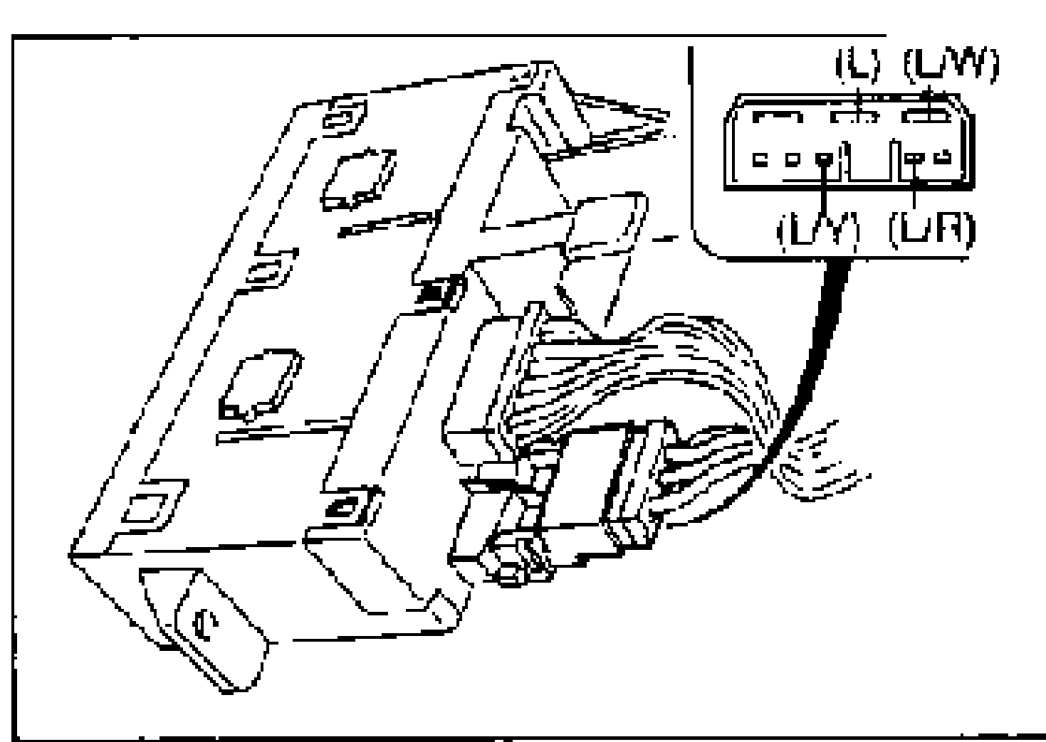
Step 2 — Fan switch connector voltage
(L/W)
VoltageB+
ActionMeasure voltage at (L) wire
(L/W)
VoltageOther
ActionRepair wiring harness (Resistor—Fan switch)
(L)
VoltageB+
ActionMeasure voltage at (L/R) wire
(L)
VoltageOther
ActionRepair wiring harness (Resistor—Fan switch)
(L/R)
VoltageB+
ActionMeasure voltage at (L/Y) wire
(L/R)
VoltageOther
ActionRepair wiring harness (Resistor—Fan switch)
(L/Y)
VoltageB+
ActionReplace fan switch (Refer to page G-44 or G-45)
(L/Y)
VoltageOther
ActionRepair wiring harness (Resistor—Fan switch)