
HEATER CONTROL UNIT - Inspection (Fan switch, A/C switch, REC switch, FRESH switch)
G-46prose procedureA/C switch inspection differs for Logic type vs Wire type heater control units.
Inspection
Fan switch
- 1Check for continuity between the terminals of the fan switch.
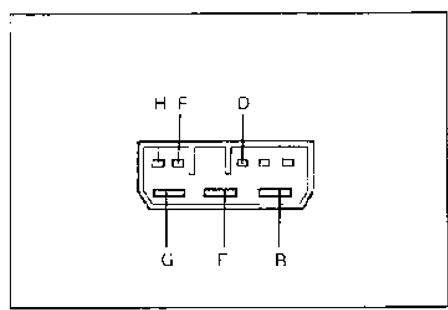
- 2If not as specified, replace the fan switch. (Refer to page G-44 or G-45.)
Fan switch terminal continuity (O—O: Continuity)
OFF
B
D
F
E
G
H
1
BO
DO
F
E
G
H
2
BO
D
FO
E
G
HO
3
BO
D
F
E
GO
HO
4
BO
D
F
EO
G
HO
NOTE
O—O : Continuity
A/C switch (Logic type)
- 1Check for continuity between the terminals of the heater control unit.
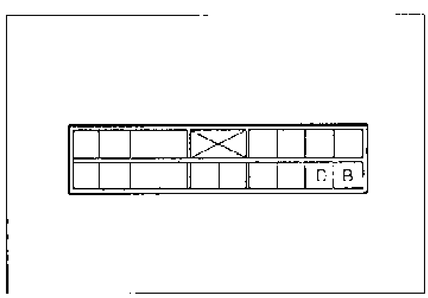
- 2If not as specified, replace the heater control unit. (Refer to page G-43.)
A/C switch (Logic type) continuity (O—O: Continuity)
OFF
B
D
ON
BO
DO
A/C switch (Wire type)
- 1Remove the A/C switch from the switch panel. (Refer to page G-45.)
- 2Check for continuity between the terminals of the A/C switch.
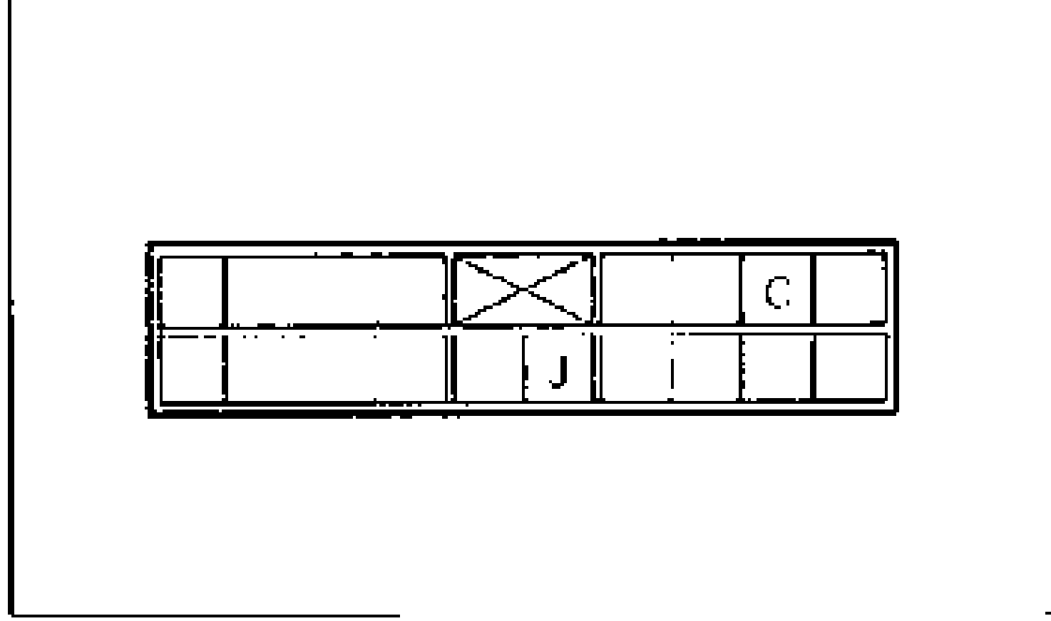
- 3If not as specified, replace the A/C switch. (Refer to page G-45.)
A/C switch (Wire type) continuity (O—O: Continuity)
OFF
D
E
ON
DO
EO
NOTE
O—O : Continuity
REC switch
- 1Remove the heater control unit. (Refer to page G-43.)
- 2Operate the REC switch and check for continuity between terminals C and J of the heater control unit.
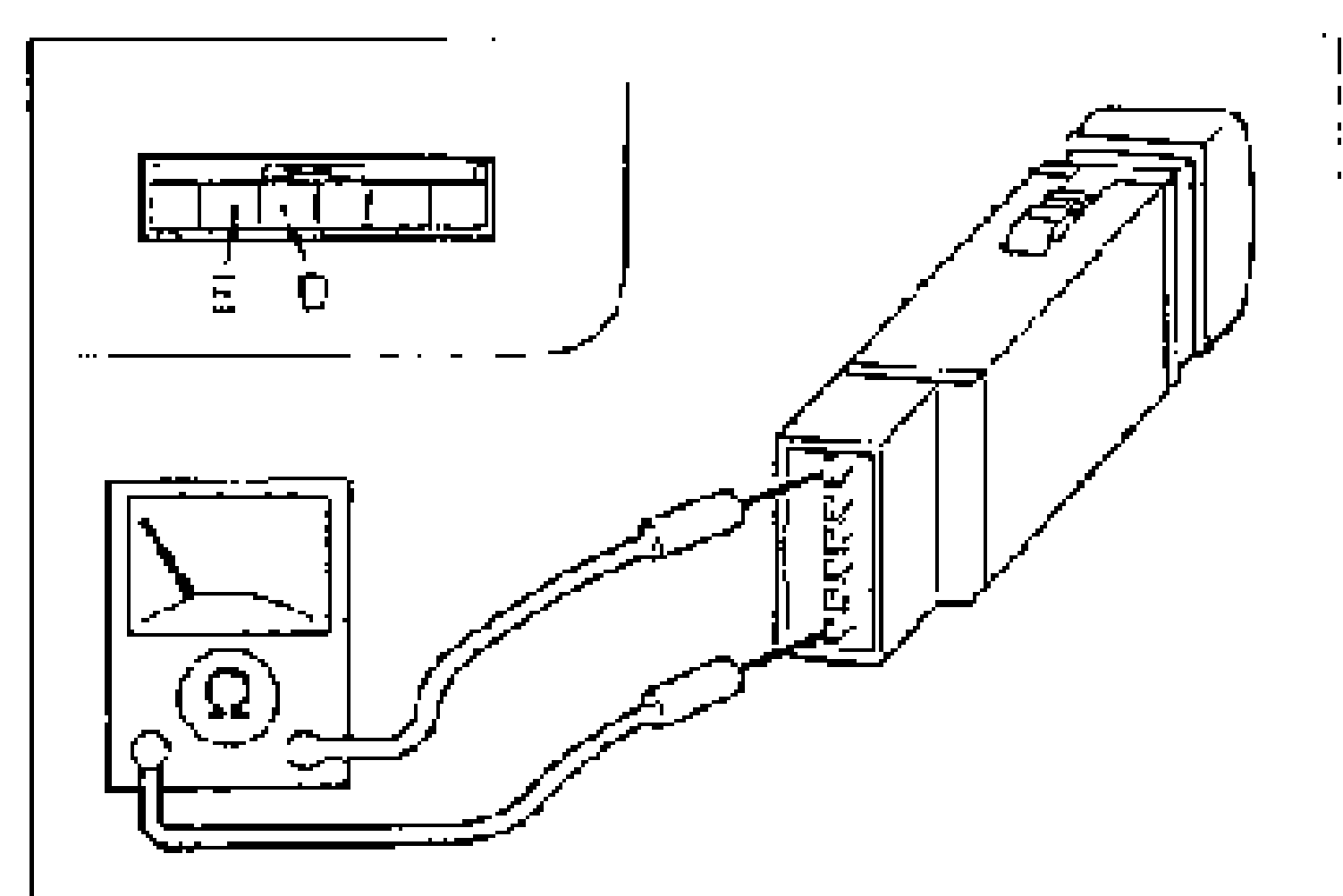
- 3If not as specified, replace the heater control unit. (Refer to page G-43.)
REC switch continuity
OFF
ContinuityNo
ON
ContinuityYes
FRESH switch
- 1Remove the heater control unit. (Refer to page G-43.)
- 2Operate the FRESH switch and check for continuity between terminals A and J of the heater control unit.
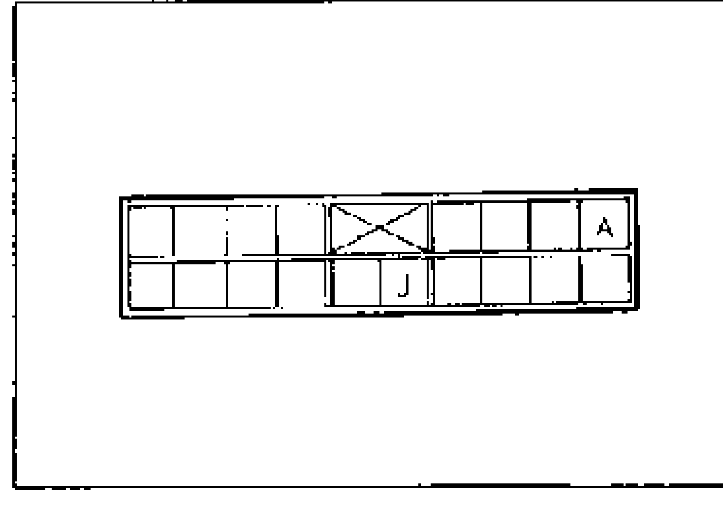
- 3If not as specified, replace the heater control unit. (Refer to page G-43.)
FRESH switch continuity
OFF
ContinuityNo
ON
ContinuityYes