
AIR CONDITIONER — Shaft seal and seal plate
G-60prose procedureShaft seal and seal plate
- 1Clean the shaft seal contacting face of the A/C compressor with cleaning solvent. Do not use a cloth. Keep dirt and solvent out of the A/C compressor. If refrigerant oil spills from the A/C compressor, refill with the same amount of oil.
- 2Clean the new shaft seal thoroughly with cleaning solvent.
- 3Lubricate the shaft seal with clean compressor oil (ATMOS GU10) and install it on the SST. Do not touch the sealing surfaces of the shaft seal after lubrication.
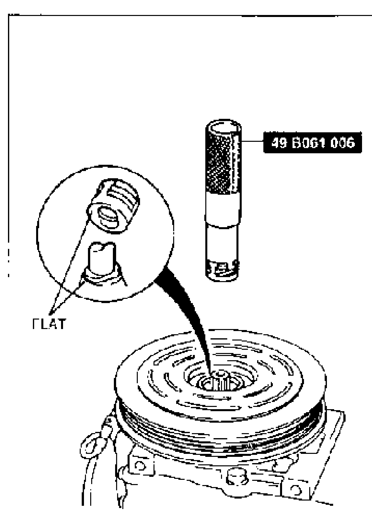 49 B061 006
 - 4Liberally lubricate the compressor shaft with compressor oil.
- 5Align the seal case flats with the shaft flats and install the shaft seal onto the compressor shaft.
- 6Clean the shaft seal plate with cleaning solvent.
- 7Lubricate the seal plate with clean refrigerant oil (ATMOS GU10). Do not touch the sealing surface of the seal plate after lubrication.
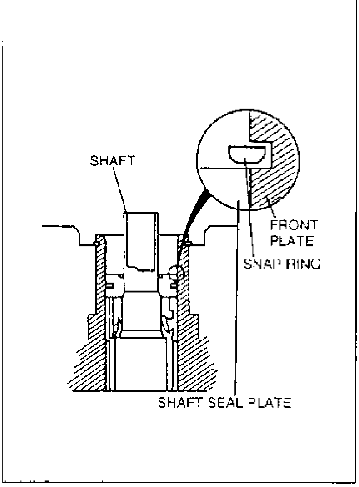
- 8Slide the seal plate into the A/C compressor by hand as far as possible.
- 9Press the seal plate with the grip side of the SST.
- 10Install the snap ring with its chamfered edge inside.
- 11Press the snap ring with the grip side of the SST, and then install the felt seal. Make sure the snap ring is seated correctly in its groove.
- 12Install the shim(s).
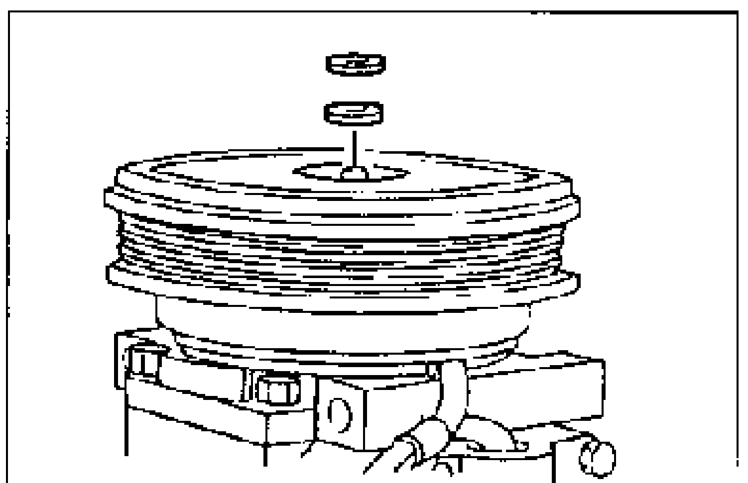
- 13Install the pressure plate.
- 14Measure the clearance between the pulley and the pressure plate all the way around. If the clearance is not as specified, add or remove the shim(s) as required.
| Specification | Value |
|---|---|
| Clearancebetween pulley and pressure plate | 0.4—0.5mm {0.016—0.020 in} |
Clearancebetween pulley and pressure plate
0.4—0.5mm {0.016—0.020 in}
Shim
B455 61 L15
Thickness mm {in}0.2 {0.008}
B456 61 L15
Thickness mm {in}0.5 {0.020}