Mazda MX-3 silhouetteMX-3

Air Conditioner — Connector Locations

G-72component photo

CONNECTOR LOCATIONS

Component LocationFig. fig1

A/C system connector and component locations in the dash harness and engine compartment.
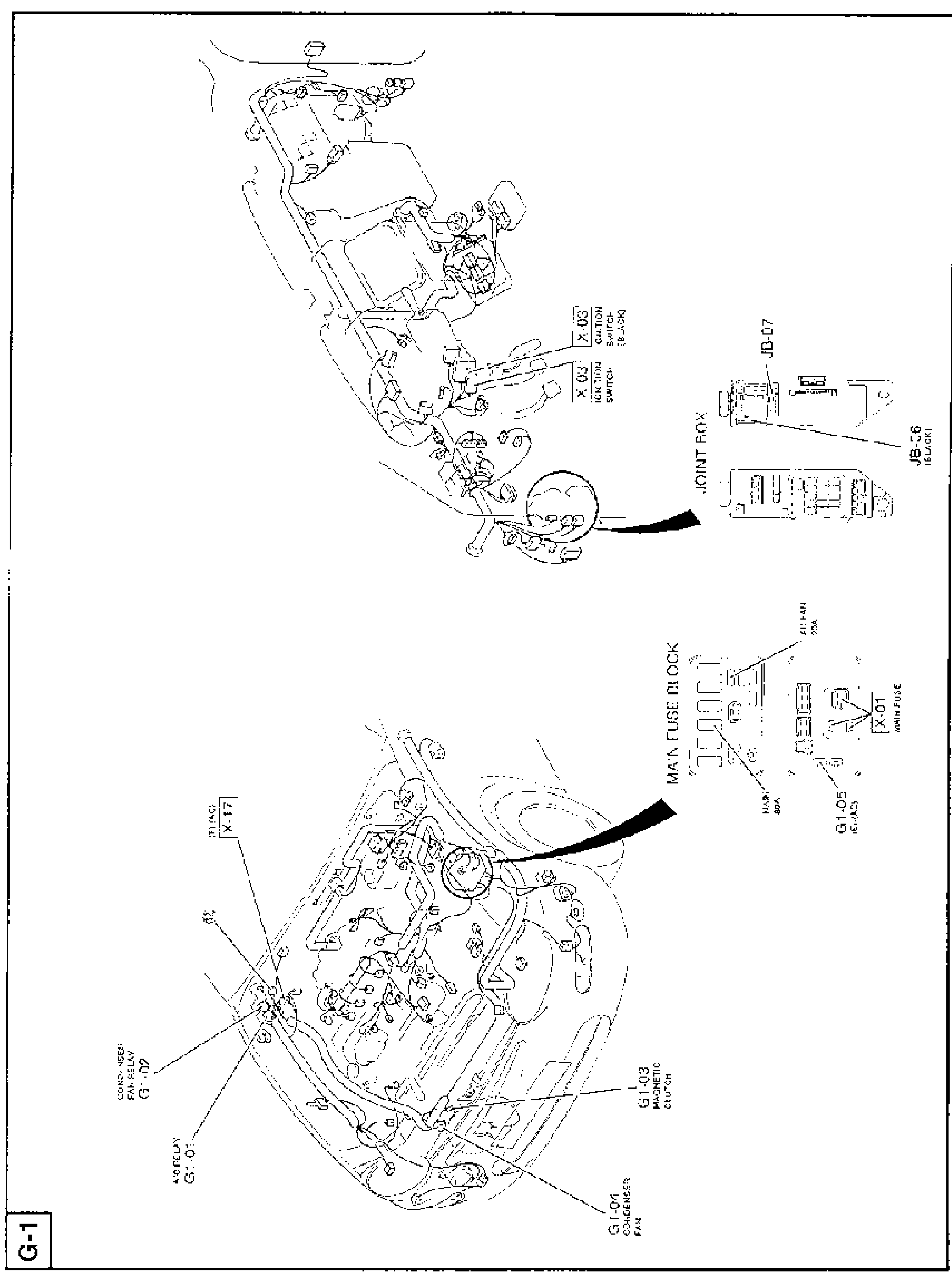
Connector-location illustration (rotated/landscape) for the A/C system. Top illustration shows the dash/engine harness with callouts to ignition switch connectors X-03 / X-03 (ignition switch, black), the joint box connectors JB-07 and JB-06 (black), and the joint box. Bottom illustration shows the engine compartment harness with callouts to the condenser fan relay G1-02, A/C relay G1-01, connector X-17 (black), condenser fan G1-04, magnetic clutch G1-03, the main fuse block (A/C FAN 30A, MAIN 80A, MAIN FUSE), connector X-01, and G1-05 (black). Arrows point from circled detail areas to the enlarged connector views.
G-1
1X-03(Ignition switch connector (black))
2X-03(Ignition switch connector)
3JB-07(Joint box connector)
4JB-06(Joint box connector (black))
5G1-02(Condenser fan relay)
6G1-01(A/C relay)
7X-17(Connector (black))
8G1-04(Condenser fan)
9G1-03(Magnetic clutch)
10G1-05(Connector (black))
11X-01(Main fuse connector)
12MAIN FUSE BLOCK(A/C FAN 30A, MAIN 80A, MAIN FUSE)

Search Manual

Search pages, specs, and procedures