
MODE switch / AIR INTAKE WIRE / AIRFLOW MODE WIRE
G-47prose procedureMODE switch
- 1Remove the heater control unit. (Refer to page G-43.)
- 2Press the MODE switch and check for continuity between the terminals of the heater control unit.
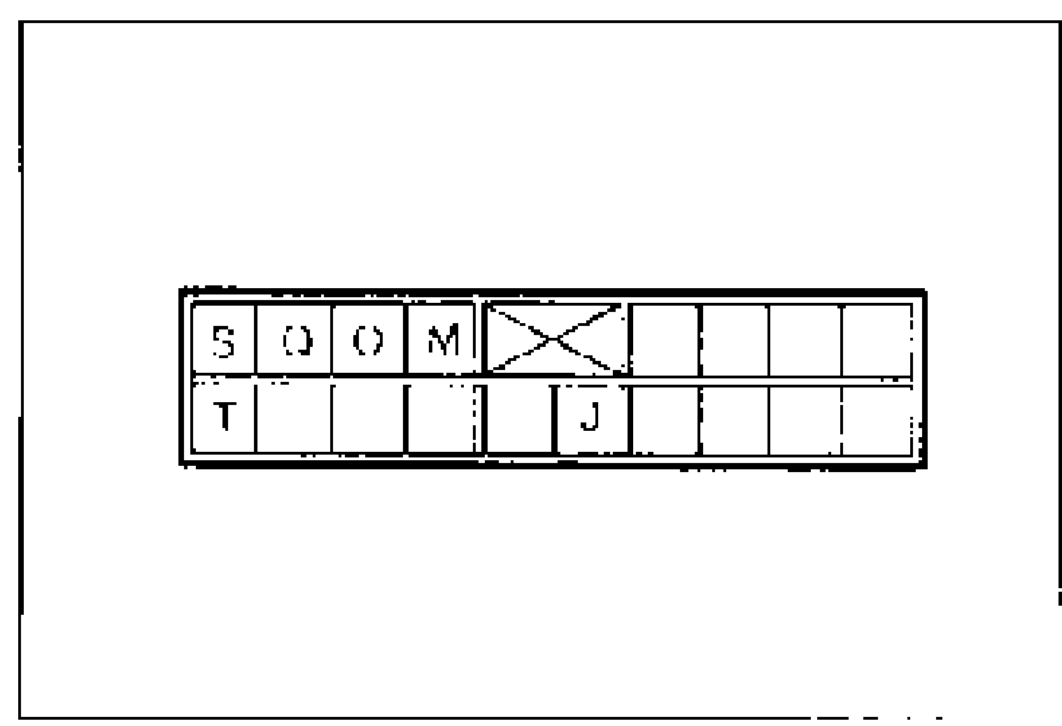
- 3If not as specified, replace the heater control unit. (Refer to page G-43.)
MODE switch terminal continuity (O—O: Continuity)
VENT
JO
TO
S
Q
O
M
B/L
JO
T
SO
Q
O
M
HEAT
JO
T
S
QO
O
M
H/D
JO
T
S
Q
OO
M
DEF
JO
T
S
Q
O
MO
NOTE
O—O : Continuity
AIR INTAKE WIRE
Adjustment
Air Intake Wire Adjustment
- 1Set the REC/FRESH lever to FRESH.
- 2Connect the air intake wire to the intake door link.
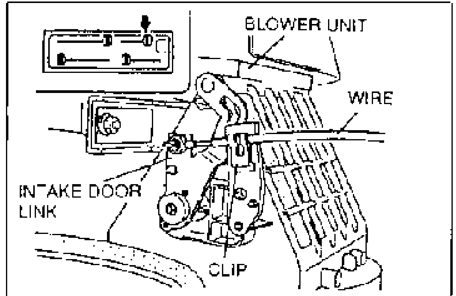
- 3Set the door at the FRESH position and clamp the wire into place.
- 4Verify that the REC/FRESH lever moves its full stroke.
AIRFLOW MODE WIRE
Adjustment
Airflow Mode Wire Adjustment
- 1Set the mode lever at DEFROST.
- 2Remove the airflow mode wire from clip A.
- 3Align set pin hole B of the link with the corresponding hole of the heater unit. Insert a 6 mm (0.24 in) pin to fix the link in the correct position.
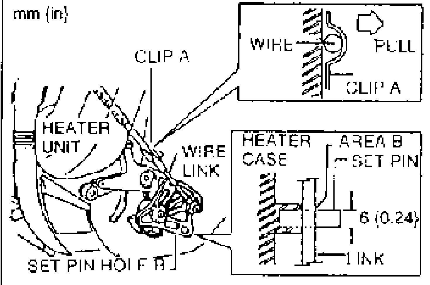
- 4Verify that the mode lever is in the defrost position.Do not push the inner wire of the airflow mode wire when setting. If pushed, the wire may be deformed, preventing the correct setting.
- 5Set the airflow mode wire against clip A as shown. Pull the airflow mode wire slightly in direction a. Press areas b and c simultaneously when setting the wire into the clip.
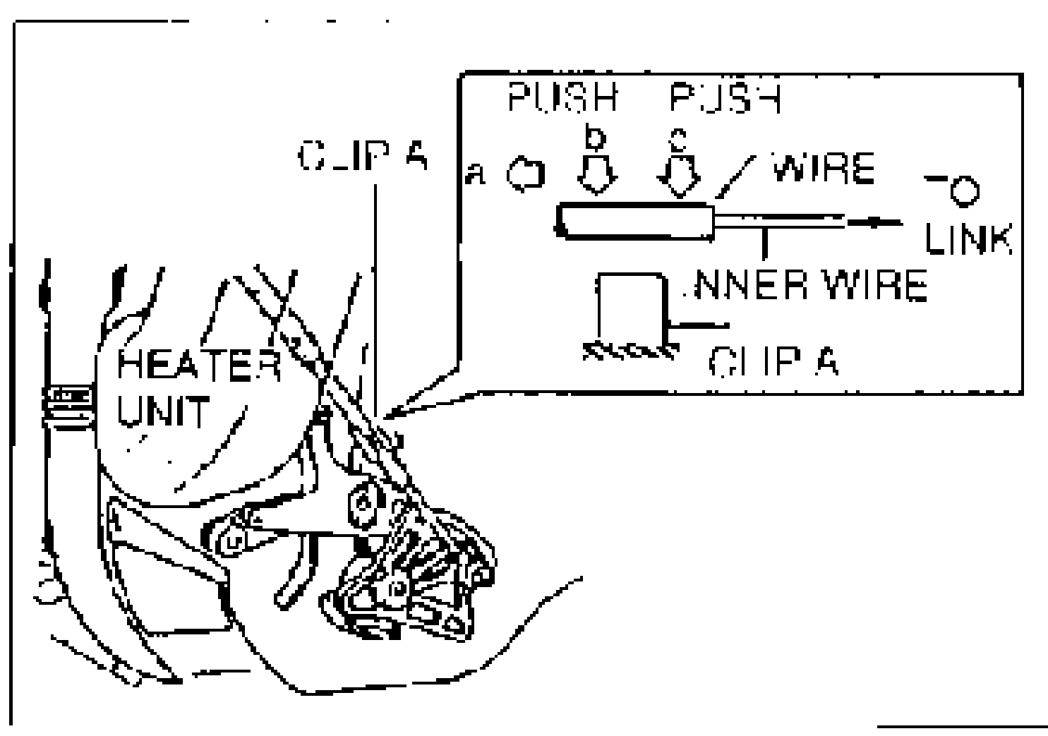
- 6Remove the set pin.
- 7Verify that the mode lever functions correctly. If not, pull the airflow mode wire 2 mm (0.08 in) in direction a.
- 8Verify that the mode lever functions correctly.