
A/C COMPRESSOR — Thermal protector / Assembly notes
G-58prose procedureThermal protector
Remove the snap ring and push the protector out from its back side to remove it. Do not pull on the wiring harness.
Assembly note
Discharge valve and valve stopper
Discharge valve and valve stopper assembly note
- 1Replace the O-ring and gasket.
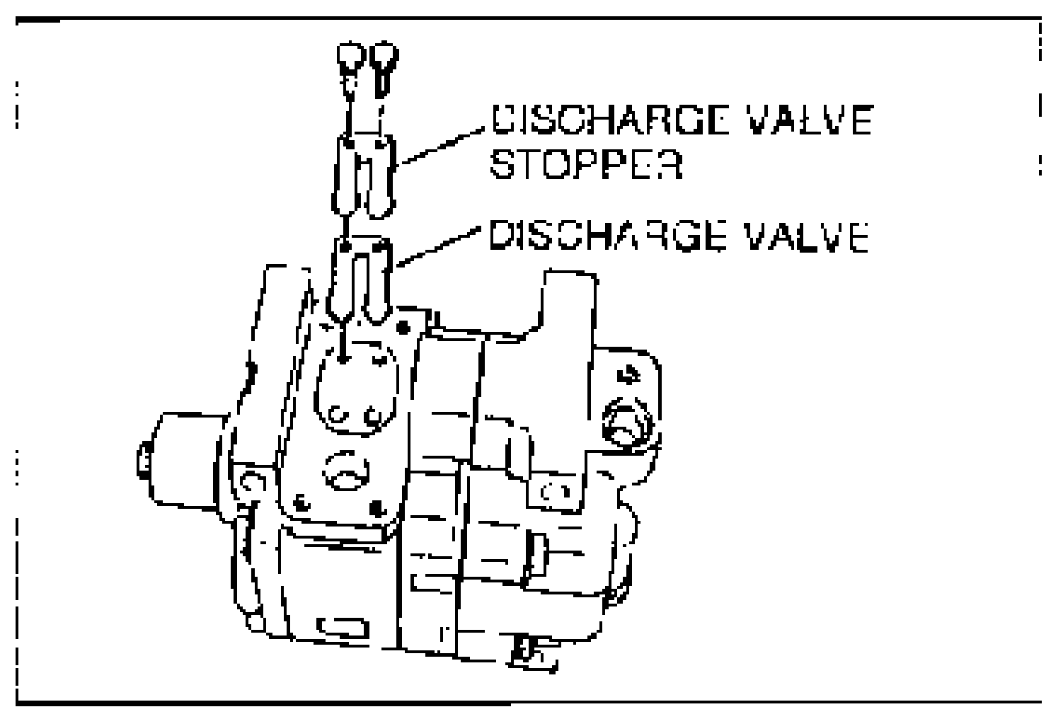
- 2Make sure the compressor body and surfaces of the discharge valve and valve stopper are free from foreign material before installing them.Tightening torque: 2.9 N.m {30 kgf.cm, 26 in.lbf}
- 3Plug the suction and discharge ports with the caps.
Thermal protector
Thermal protector assembly note
- 1Make sure the O-ring is free from foreign material. Apply compressor oil to the O-ring and fit it into the groove securely.
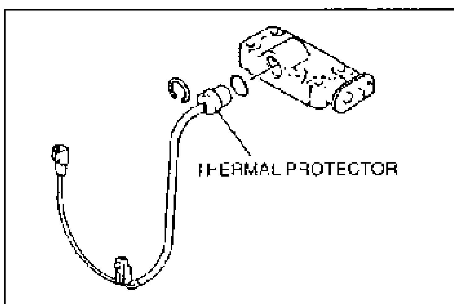
- 2Check for continuity between the protector terminals.
- 3Install the snap ring so that its chamfered edge faces the thermal protector. Make sure the snap ring is seated securely in its groove.
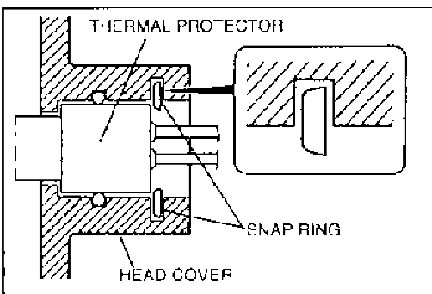
- 4Install the thermal protector so that its two lead wire outlet sections are horizontal, as shown on the left.
| Specification | Value |
|---|---|
| Tightening torque (discharge valve / valve stopper) | ≈28N·m |
Tightening torque (discharge valve / valve stopper)
28N·m