
AIRFLOW MODE ACTUATOR
G-39prose procedureInspection
- 1Remove the cooling unit. (Refer to page G-67.)
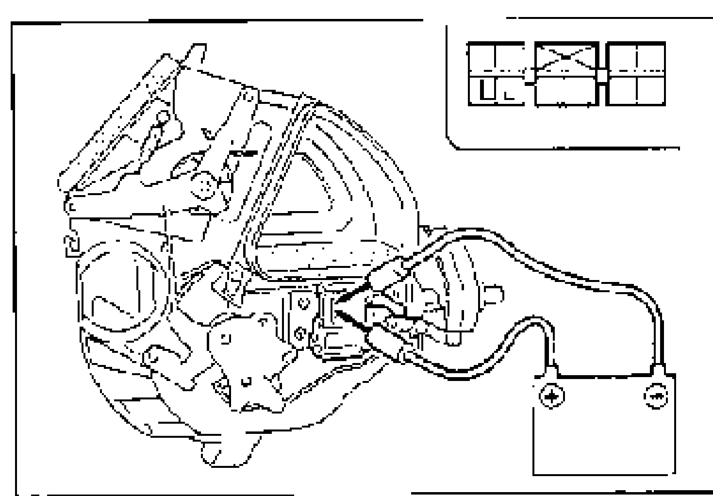
- 2Disconnect the airflow mode actuator connector.
- 3Connect battery positive voltage to terminals L and J and check the operation of the airflow mode actuator.B+: Battery positive voltage
- 4If not as specified, replace the airflow mode actuator. (Refer to page G-38.)
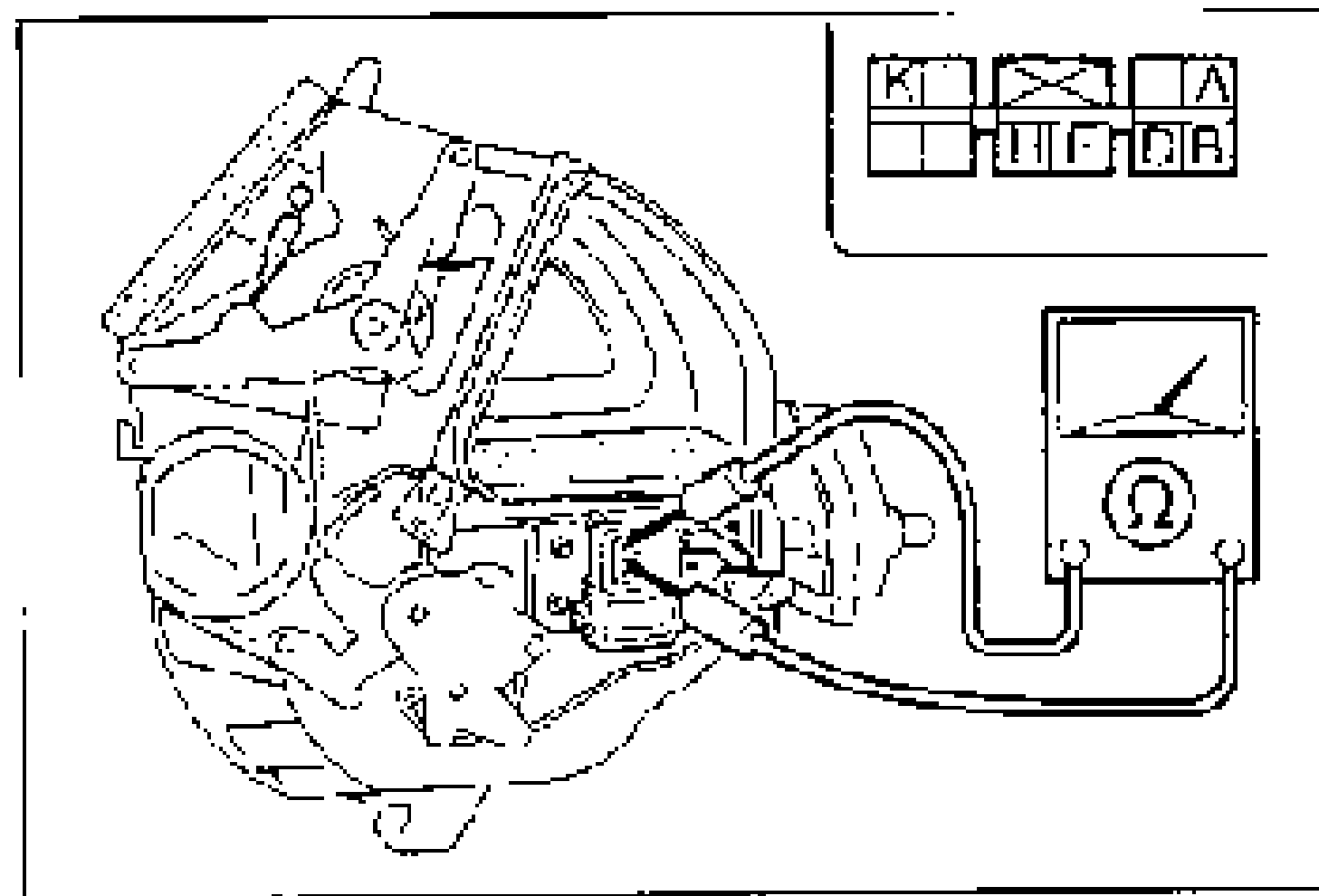
- 5Check for continuity between the terminals of the airflow mode actuator.
- 6If not as specified, replace the airflow mode actuator. (Refer to page G-38.)
Actuator operation (B+: Battery positive voltage)
L
GNDJ
Actuator operationVENT → B/L → HEAT → H/D → DEF
J
GNDL
Actuator operationDEF → H/D → HEAT → B/L → VENT
Continuity between airflow mode actuator terminals (O—O: Continuity)
VENT
K
I
HO
AO
BO
CO—O
FO
B/L
KO—O
IO
H
AO
BO—O
CO
FO
HEAT
KO
IO—O
HO
A
BO
CO—O
FO
H/D
KO
IO
HO—O
AO
B
CO—O
FO
DEF
KO—O
IO—O
HO—O
AO—O
B
C
F
NOTE
O—O : Continuity