
ANTI-LOCK BRAKE SYSTEM
P-73prose procedureABS relay (continued)
- 4If not as specified, replace the ABS relay.
ABS relay (Motor relay)
- 1Measure the resistance between terminals (e) and (h) or between (a) and (h) of the ABS relay connector.
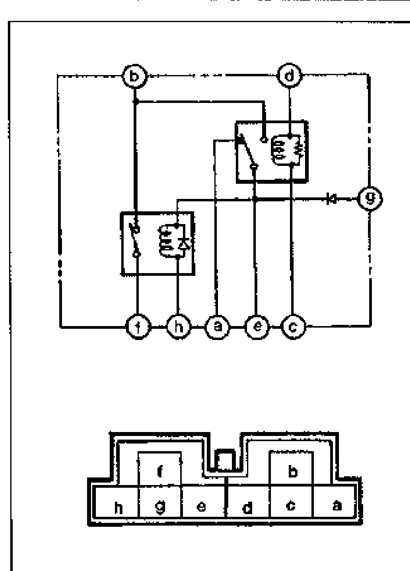
- 2Check continuity between terminals (b) and (f).
- 3Apply 12V to terminals (g) (+) and (h) (−). Check for continuity between terminals (b) and (f).
- 4If not as specified, replace the ABS relay.
| Specification | Value |
|---|---|
| Resistancebetween terminals (e) and (h) or (a) and (h) | 50–90Ω |
Resistancebetween terminals (e) and (h) or (a) and (h)
50–90Ω
Continuity (no power applied)
b–f
ContinuityNo
Continuity (12V applied to g(+) and h(−))
b–f
ContinuityYes