
ANTI-LOCK BRAKE SYSTEM — Check motor harness / motor / solenoid valve harness
P-62prose procedureCheck motor harness at ABS control module
- 1Turn the ignition switch OFF, and disconnect the ABS control module connector (12 pin).
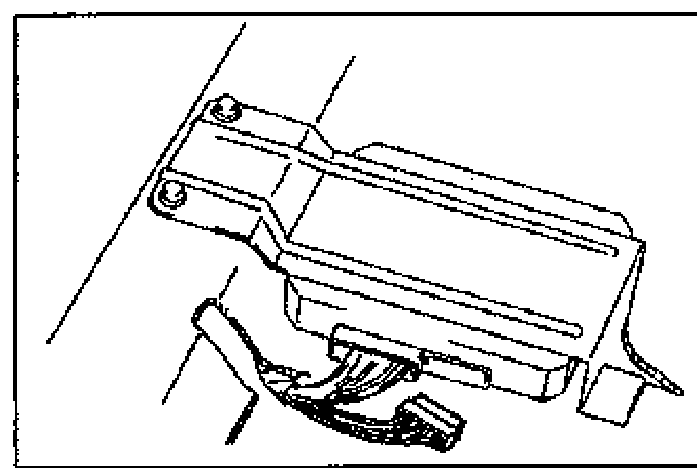
- 2Measure the resistance between 1 L terminal of the ABS control module connector and a ground.
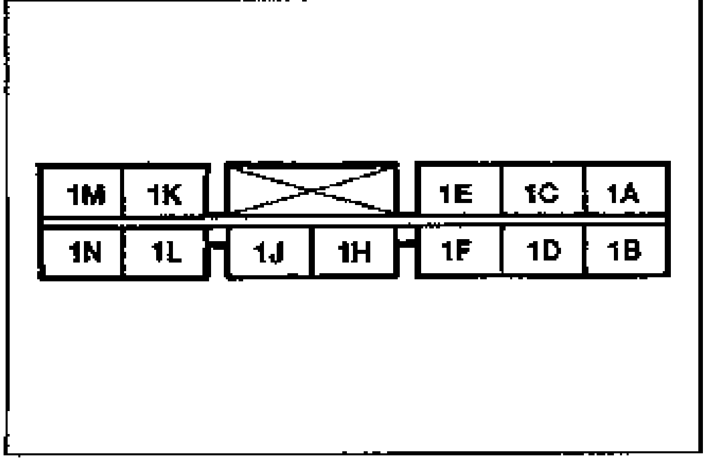
- 3If not as specified, check the wiring harness between the ABS motor and the ABS control module and check the motor.
| Specification | Value |
|---|---|
| Resistancebetween 1L terminal and ground | 1Ω max. |
Resistancebetween 1L terminal and ground
1Ω max.
Check motor at ABS hydraulic unit
- 1Turn the ignition switch OFF.
- 2Disconnect the ABS hydraulic unit connector (2 pin).
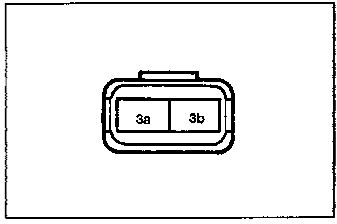
- 3Measure the resistance between the connector terminals.
- 4Verify that the motor operates when applying 12V to connector (2 pin).
- 5If not as specified, replace the ABS hydraulic unit.
| Specification | Value |
|---|---|
| Resistancebetween connector terminals (2 pin) | 1Ω max. |
Resistancebetween connector terminals (2 pin)
1Ω max.
Check solenoid valve harness of ABS control module
- 1Turn the ignition switch OFF.
- 2Measure the resistance between a ground and the following terminals at the ABS control module connector (12 pin). Terminal: 1A, Right rear; 1B, Left front; 1C, Right front; 1D, Left rear
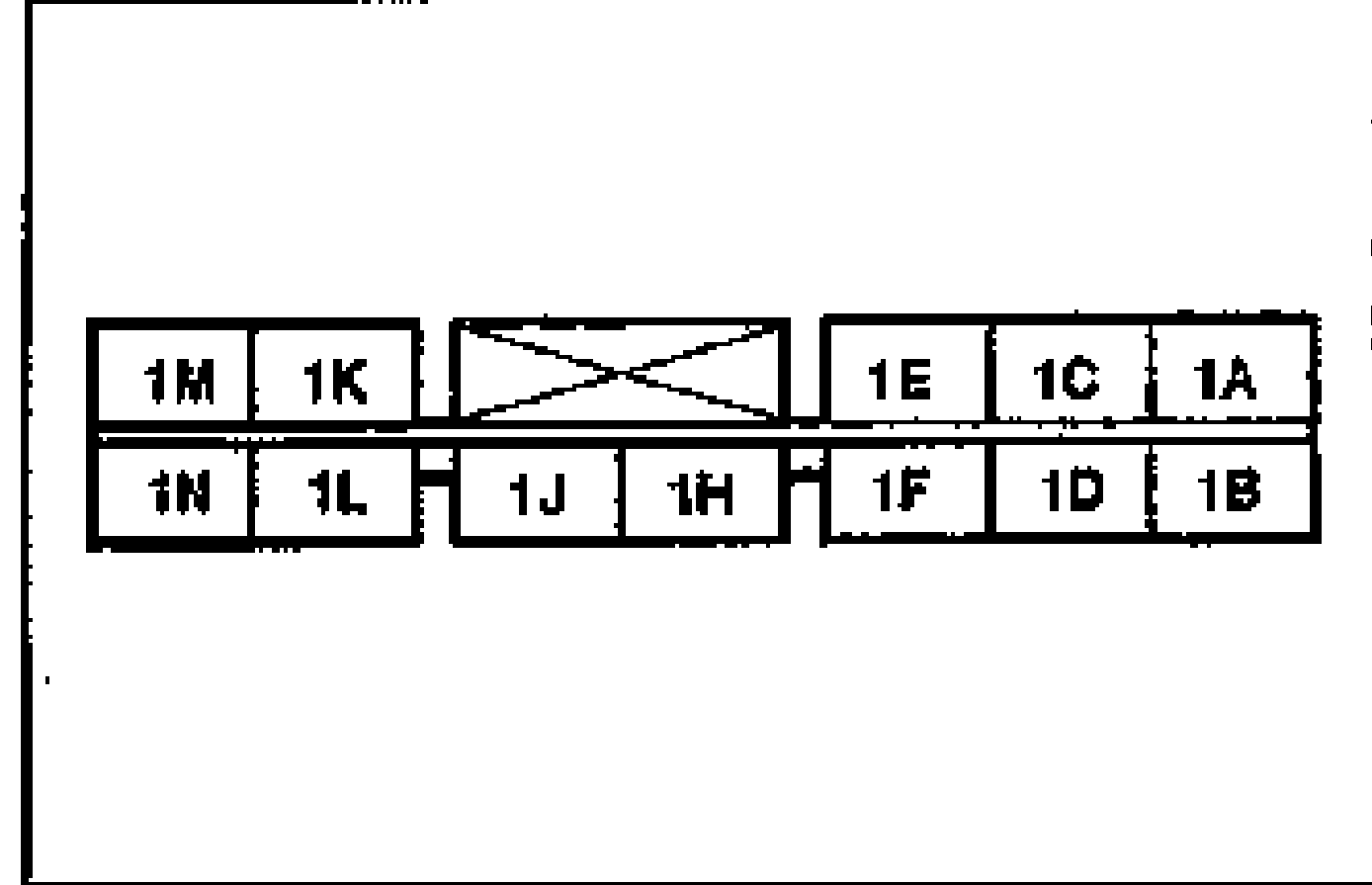
- 3If not as specified, check the wiring harness between the hydraulic unit connector (8 pin) and the ABS control module.
| Specification | Value |
|---|---|
| Resistancebetween ground and terminals 1A/1B/1C/1D | Approx. 3Ω |
Resistancebetween ground and terminals 1A/1B/1C/1D
Approx. 3Ω