
ANTI-LOCK BRAKE SYSTEM
P-67prose procedureCheck ABS relay harness (motor relay)
- 1Inspect the fail-safe relay.
- 2Turn the ignition switch OFF and disconnect the ABS control module connector (18 pin).
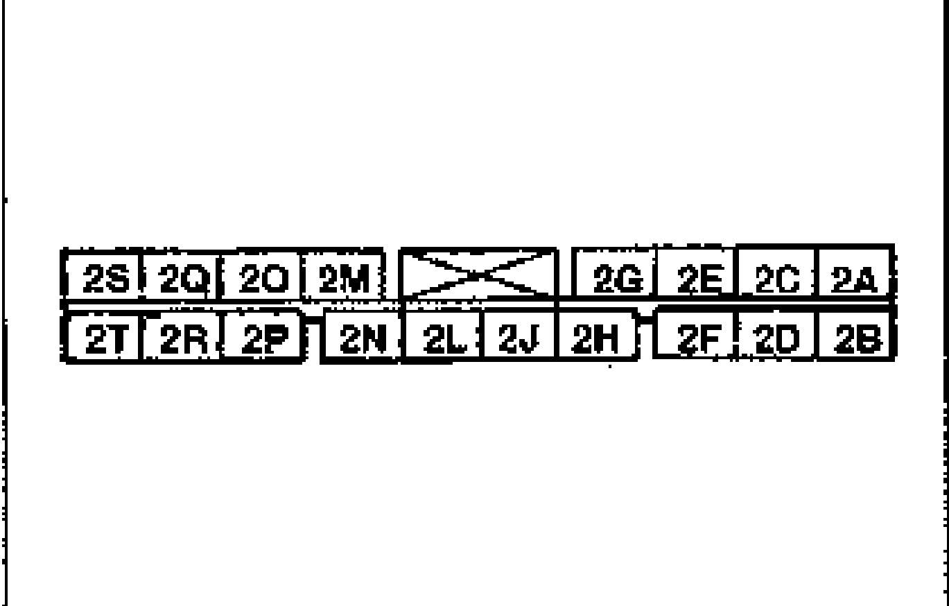
- 3Turn the ignition switch ON.
- 4Connect terminal 2J to a ground.
- 5Connect terminal 2H to a ground.
- 6Check the following points:Allowing the motor to operate for more than two seconds will damage the ABS motor.
- 7If not as specified, replace the ABS relay.
Motor relay harness check
Motor relay in ABS relay does not click when terminals grounded
ActionCheck harness between motor relay and ABS control module; Check motor relay
ABS motor does not operate
ActionCheck motor relay; Check harness between motor relay and ABS motor; Check fuse
CAUTION
Allowing the motor to operate for more than two seconds will damage the ABS motor.
Check ABS relay (motor relay)
- 1Measure the resistance between terminals (e) and (h) or between (a) and (h) of ABS relay box connector.
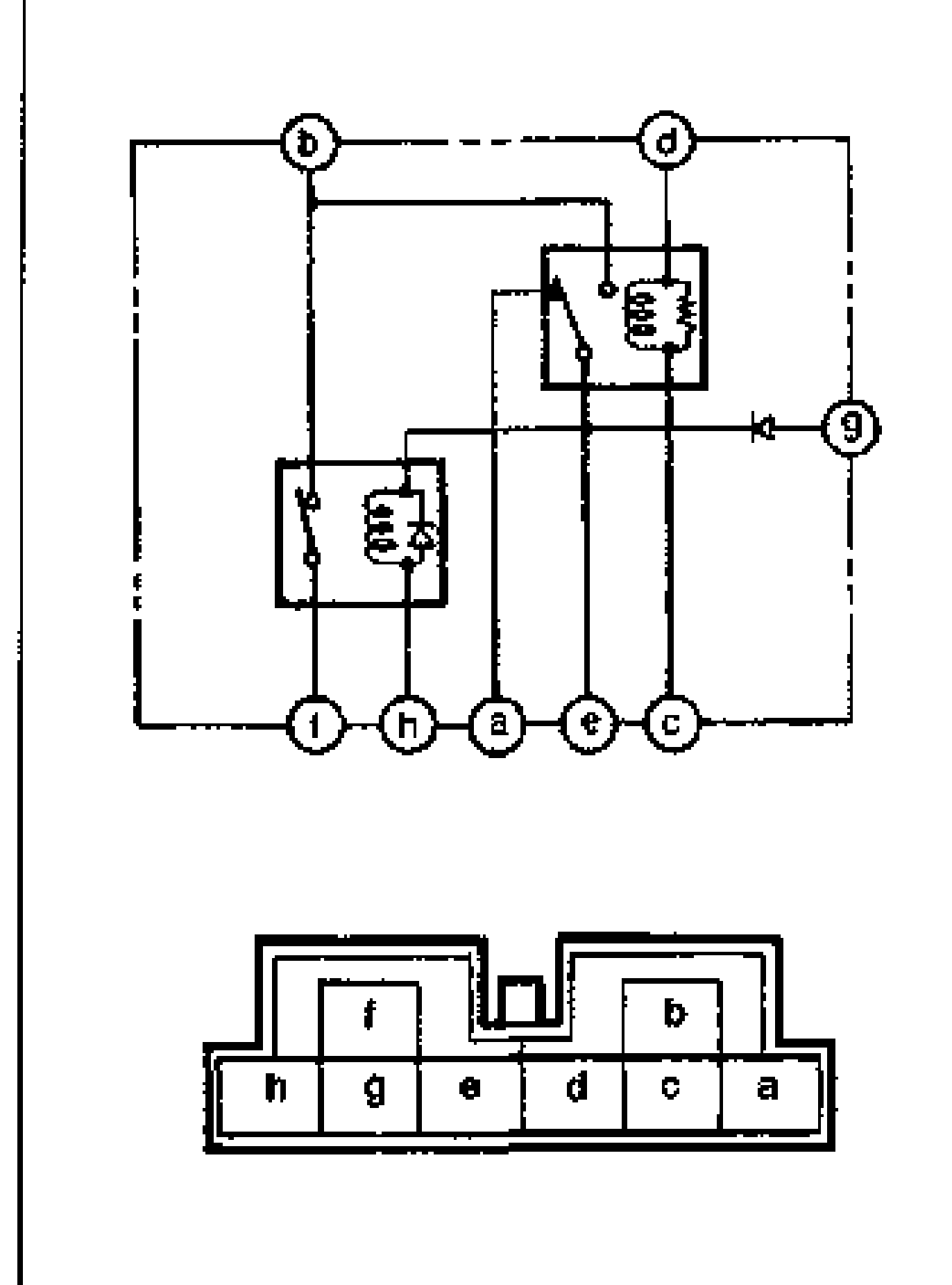
- 2Check continuity between terminals (b) and (f).
- 3Apply 12V to terminals (g) (+) and (h) (-). Check for continuity between terminals (b) and (f).
- 4If not as specified, replace the ABS relay.
| Specification | Value |
|---|---|
| Resistancebetween terminals (e)-(h) or (a)-(h) | 50-90Ω |
Resistancebetween terminals (e)-(h) or (a)-(h)
50-90Ω
Continuity (no voltage applied)
b-f
ContinuityNo
Continuity (12V applied: g(+), h(-))
b-f
ContinuityYes