
ANTI-LOCK BRAKE SYSTEM
P-69prose procedureABS HYDRAULIC UNIT
The ABS control module contains a self-diagnostic function to check the hydraulic system operation. During the diagnostic mode, the ABS control module activates the ABS hydraulic unit to reduce the hydraulic pressure of the right front, left front, right rear, left rear in sequence for 0.5 second each at intervals of 1.5 seconds.
Inspection
- 1Verify that the battery is fully charged. Verify that the ABS warning light goes out after the engine is started.
- 2If the light stays ON after the engine has started, the ABS control module detects a failure and will not activate the hydraulic unit.
- 3Turn off the engine.
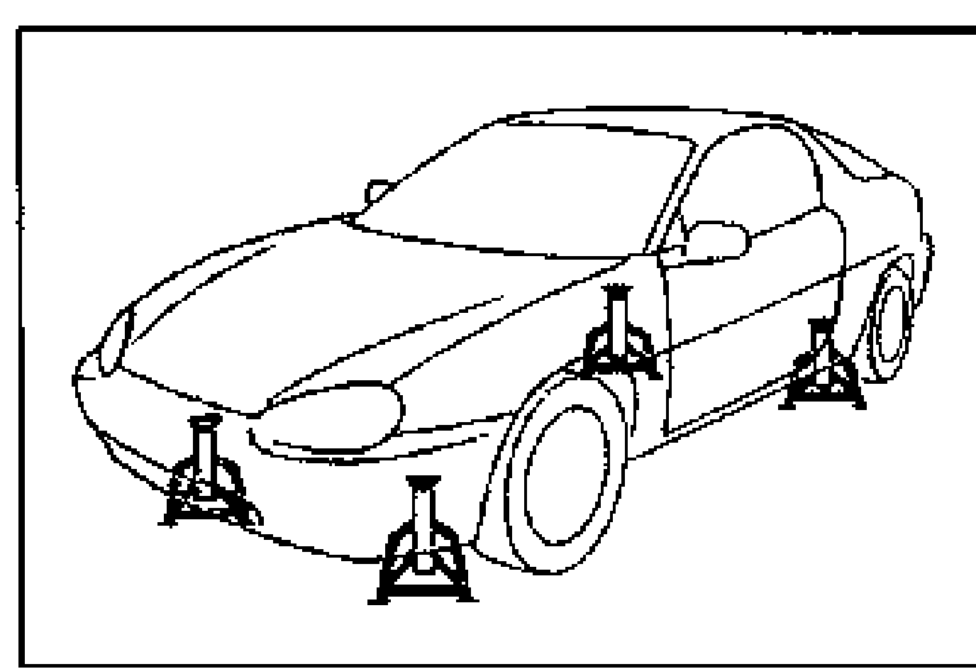
- 4On level ground, jack up the vehicle and support it evenly on safety stands. Shift the transaxle to neutral or N range.
- 5Release the parking brake.
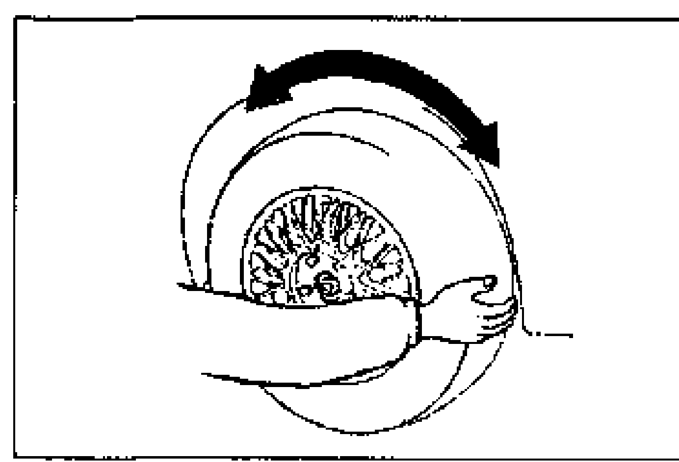
- 6Rotate the wheels by hand, and inspect for brake drag.
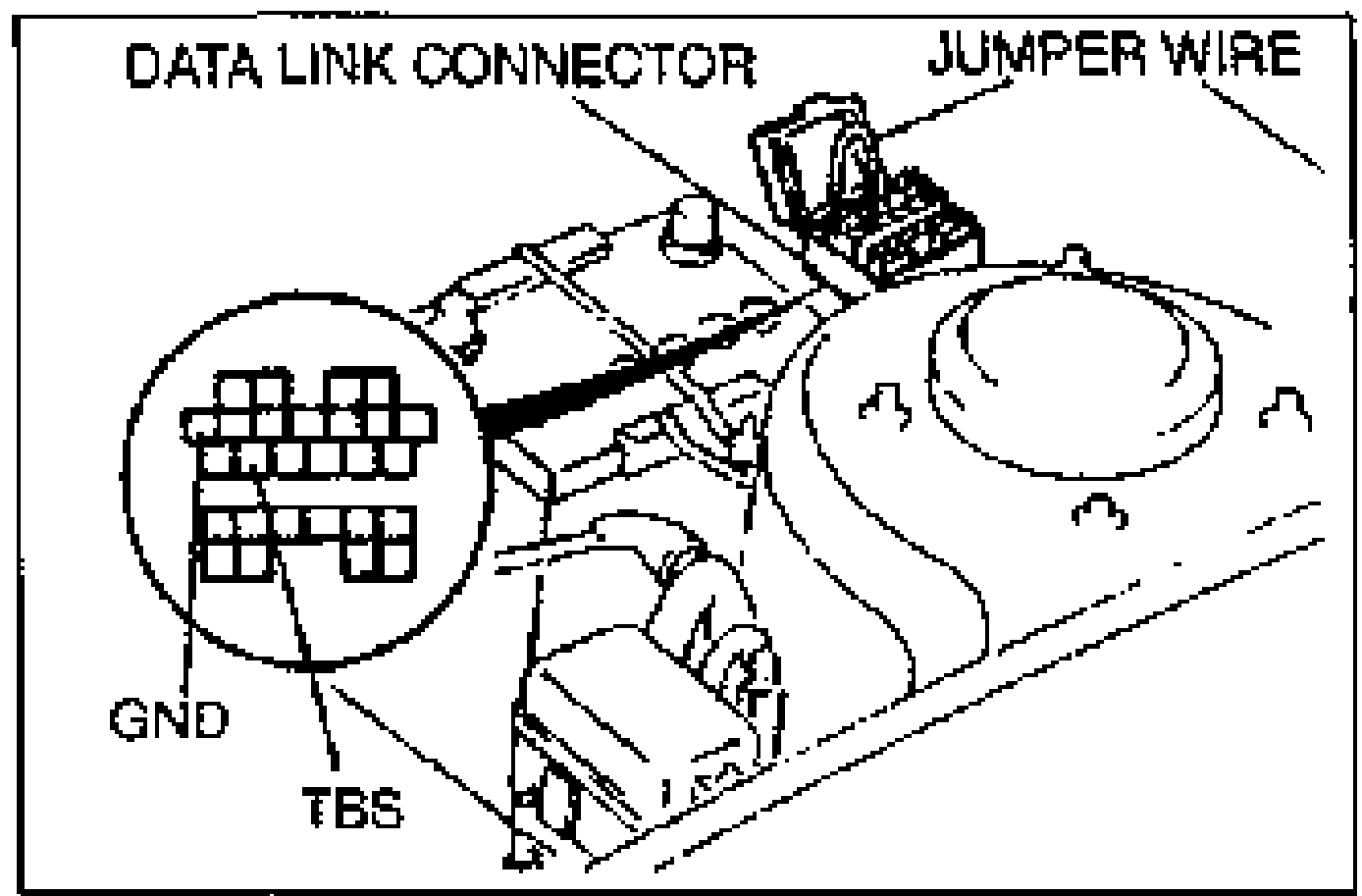
- 7Using a jumper wire, connect the TBS and GND terminals of the data link connector.
- 8Depress the brake pedal, and have an assistant verify that the right front wheel will not turn.
- 9With the brake still depressed, turn the ignition switch ON and verify that the brake is released momentarily (approx. 0.5 sec.) and the wheel turns when pressure-reduction operates.
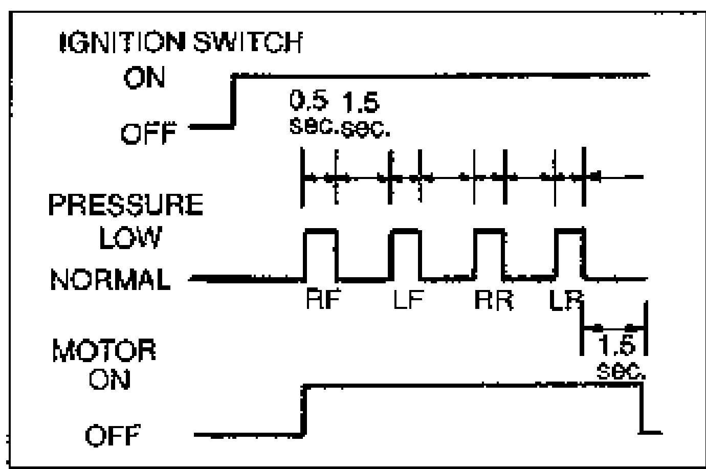
- 10Check operation of the remaining wheels in order: left front, right rear, left rear.
- 11If Steps 8, 9 and 10 show correct operation, the following systems are OK: Brake piping to ABS hydraulic unit; Braking system, including ABS hydraulic unit; Electrical system in ABS hydraulic unit (solenoid, motor, etc.); ABS control module, its output system (solenoid, relay, etc.) and harness. The following are not checked with the above steps: Input system and harness of ABS control module; Fluid leakage; Intermittent failure.
- 12Replace the ABS hydraulic unit if necessary.