
ANTI-LOCK BRAKE SYSTEM — ON-BOARD DIAGNOSIS FUNCTION
P-54prose procedureON-BOARD DIAGNOSIS FUNCTION
Inspection By Diagnostic Mode
Outline
The ABS control module contains on-board diagnosis and memory functions to watch for and indicate present and past failures. Read and note the diagnostic indications using the SSTs then take action according to the diagnostic trouble code table. (Refer to page P-56.)
Inspection procedure
- 1Connect the SSTs to the data link connector and a ground.
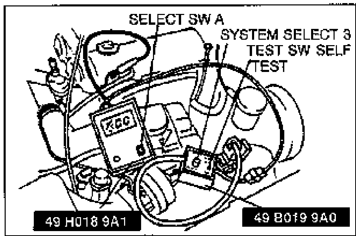
- 2Set the select switch to position A.
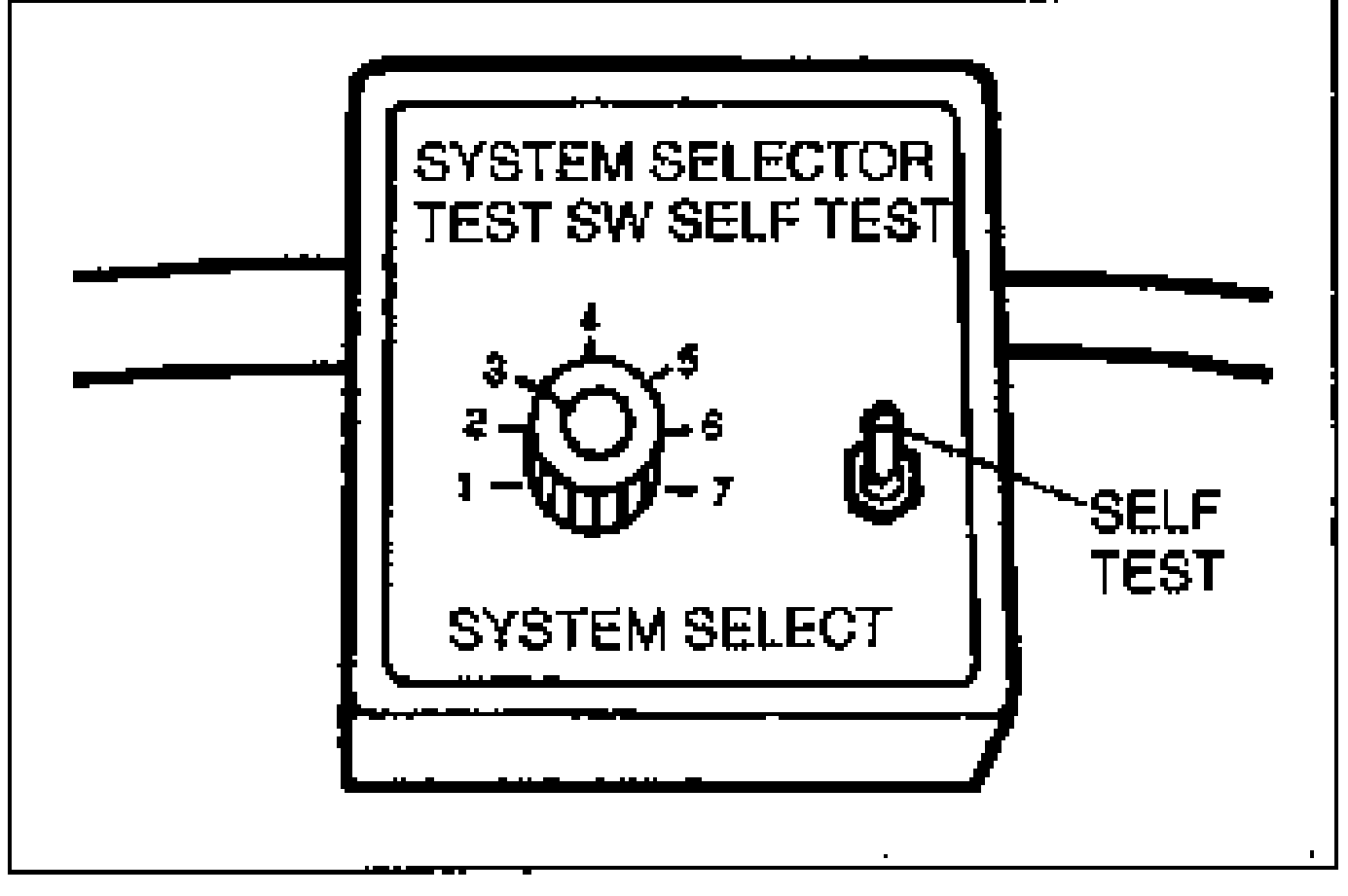
- 3Set the system selector to position 3 and SELF TEST as shown.
- 4Turn the ignition switch ON.
- 5Verify that 88 flashes on the digital display and the buzzer sounds for 3 sec. after turning the ignition switch ON.
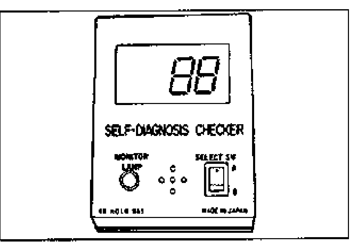
- 6If 88 does not flash, check power supply circuit, and ground wiring.
- 7If 88 flashes and the buzzer continues for more than 20 sec., check for a short circuit between terminal TBS and ground. Replace ABS control module if necessary and perform steps 3 and 4 again.
- 8Note any code numbers and check for the causes by referring to the check sequences shown on pages P-57 to P-59. Repair as necessary.
- 9After repairs, cancel the code numbers by performing "Memory Cansel." (Refer to page P-56.)