
ANTI-LOCK BRAKE SYSTEM
P-66prose procedureCheck ABS relay harness (fail-safe relay)
- 1Turn the ignition switch OFF and disconnect the ABS control module connector (18 pin).
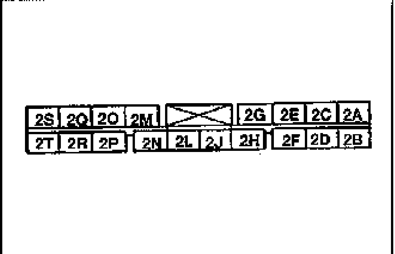
- 2Turn the ignition switch ON.
- 3Connect terminal 2J of the ABS control module connector (18 pin) to a ground.
- 4Check the following points.
Fail-safe relay harness check
Fail-safe relay in ABS relay does not click when 2J terminal grounded
ActionCheck fail-safe relay; Check harness between fail-safe relay and ABS control module
Warning light illuminates after grounding 2J terminal
ActionCheck fail-safe relay
1D (BR) terminal of ABS control module connector does not indicate 12V
ActionCheck fail-safe relay; Check harness between fail-safe relay and ABS hydraulic unit
Check ABS relay (fail-safe relay)
- 1Measure resistance between terminals (c) and (d) of ABS relay connector.
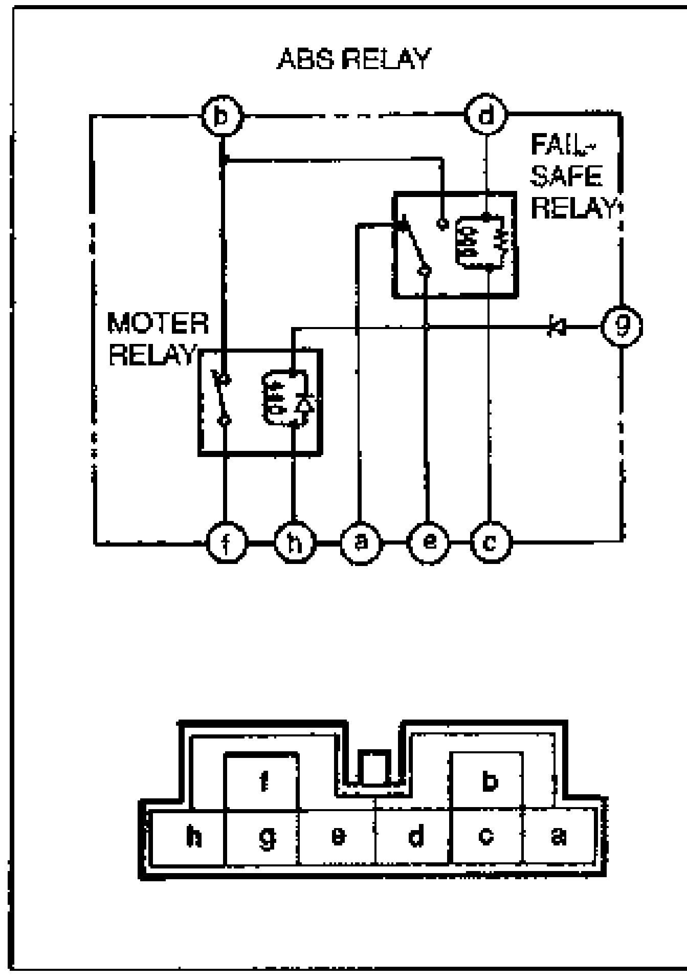
- 2Check continuity between terminals (a) and (e) and between (b) and (e).
- 3Apply 12V to terminals between d and c. Check for continuity between terminals (b) and (e) and between (a) and (e).
| Specification | Value |
|---|---|
| Resistancebetween terminals (c) and (d) | 60-100Ω |
Resistancebetween terminals (c) and (d)
60-100Ω
Continuity (no voltage applied)
a-e
ContinuityYes
b-e
ContinuityNo
Continuity (12V applied between d and c)
b-e
ContinuityYes
a-e
ContinuityNo