
CONVENTIONAL BRAKE SYSTEM
P-15prose procedurePush rod clearance inspection (continued)
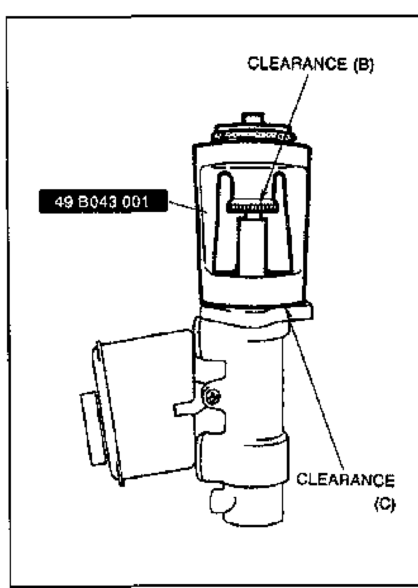
- 4Remove the SST from the power brake unit without disturbing the adjusting nut. Set the SST onto the master cylinder as shown in the figure.When pushing only use enough pressure to bottom the rod in the piston. If too much pressure is applied a false reading will occur.
 49 B043 001
 - 5Push lightly on the end of the SST gauge rod to be sure it is bottomed in the master cylinder piston, and note any clearance between the SST body and the adjusting nut (clearance B) or between the body and the master cylinder (clearance C). Adjust the push rod as necessary as outlined in "Adjustment" below.
Push rod clearance measurement result
Clearance at (B)
Push rodToo short
Clearance at (C)
Push rodToo long
No clearance at (B) or (C)
Push rodOK
Adjustment
NOTE
The threads of the push rod are specially designed so that the bolt becomes harder to turn past a certain point to prevent loosening of the bolt. Turn the bolt only within this range when adjusting.
Clearance at B
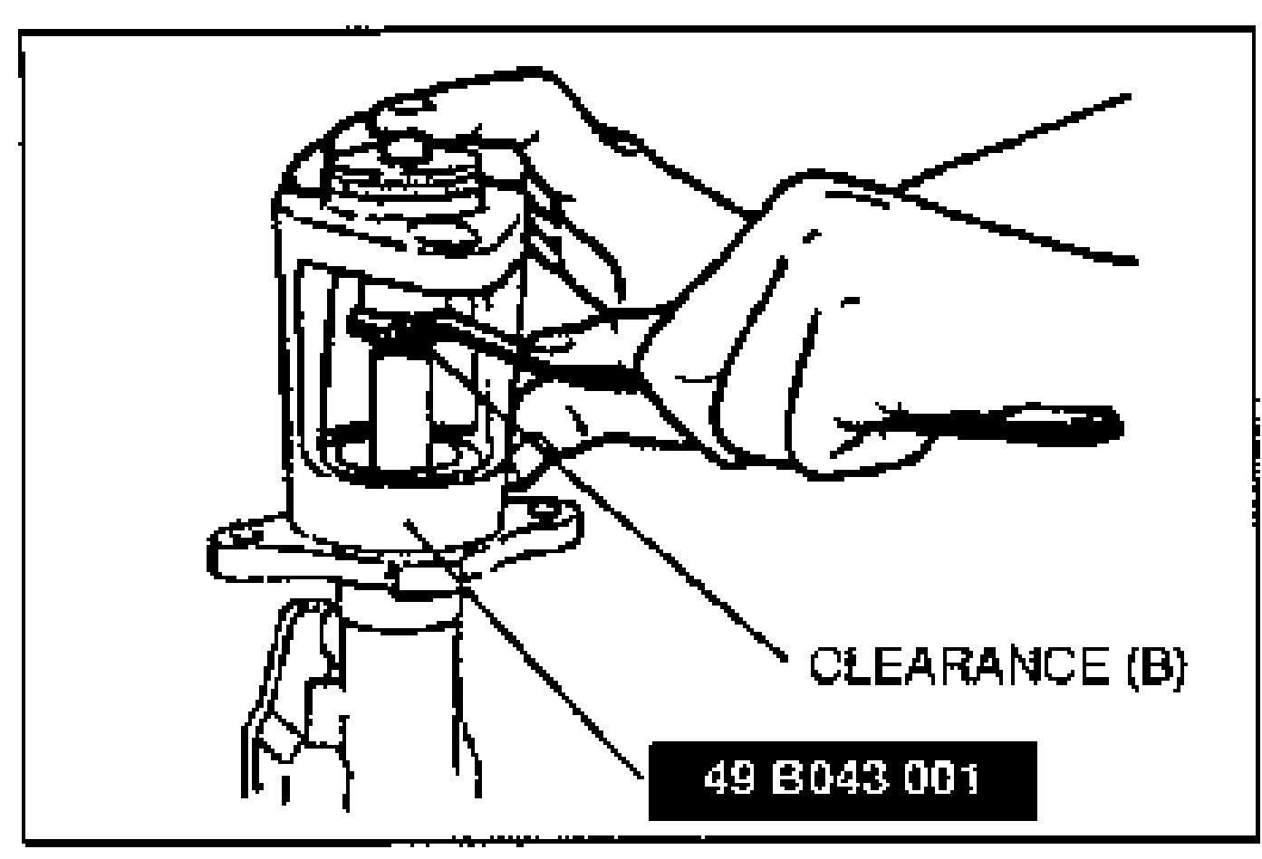
- 1Push lightly on the end of the SST gauge rod, and measure the clearance between the adjusting nut and the SST body.
 49 B043 001
 - 2Using the SSTs, turn the nut to lengthen the power brake unit push rod an amount equal to the clearance measured at B.
Clearance at C
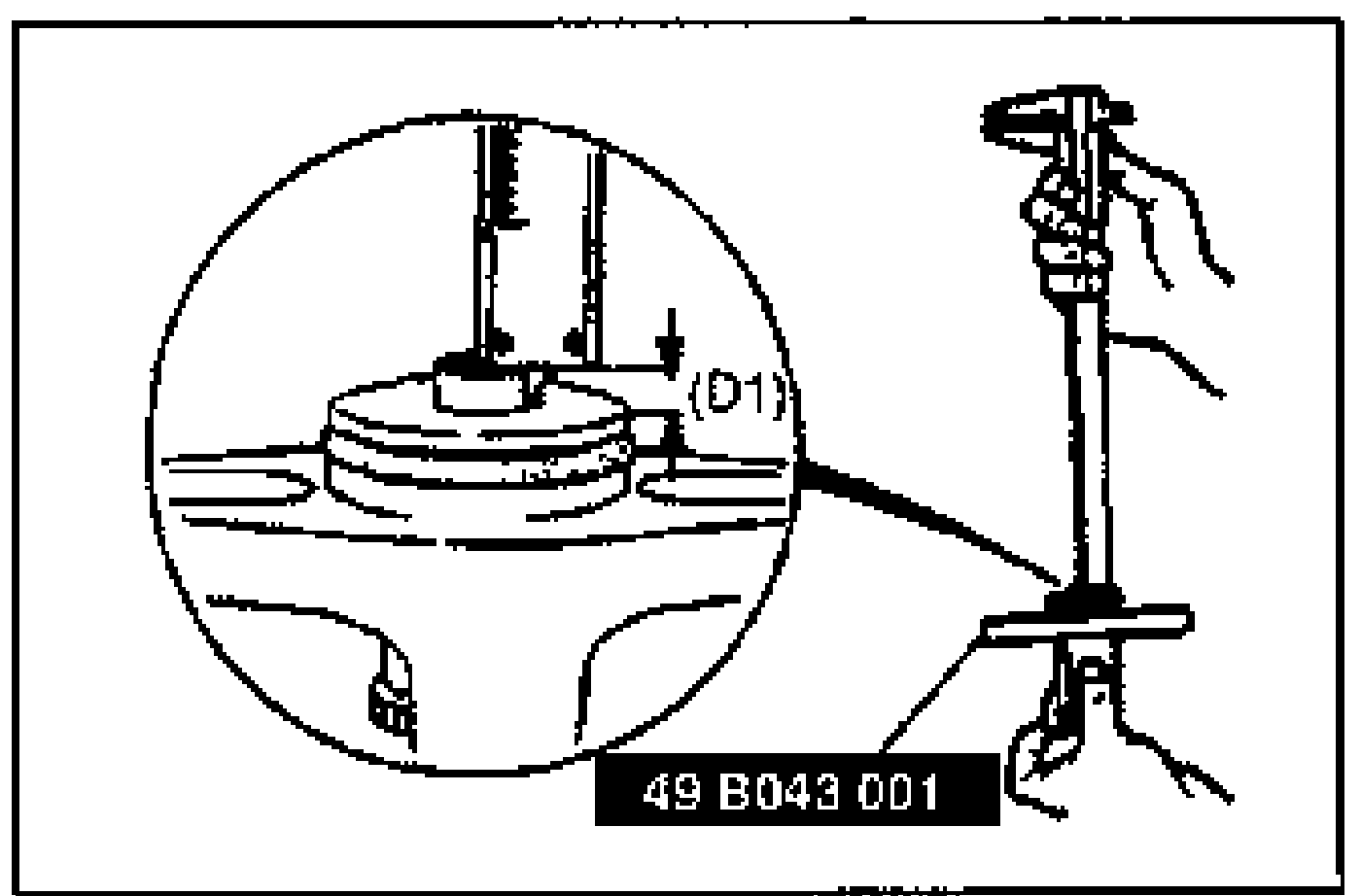
- 1Measure and record height D1 of the gauge rod.
 49 B043 001