
CONVENTIONAL BRAKE SYSTEM
P-13prose procedurePush rod adjustment (continued)
- 2Apply 66.7 kPa {500 mmHg, 19.7 inHg} vacuum to the power brake unit with a vacuum pump.
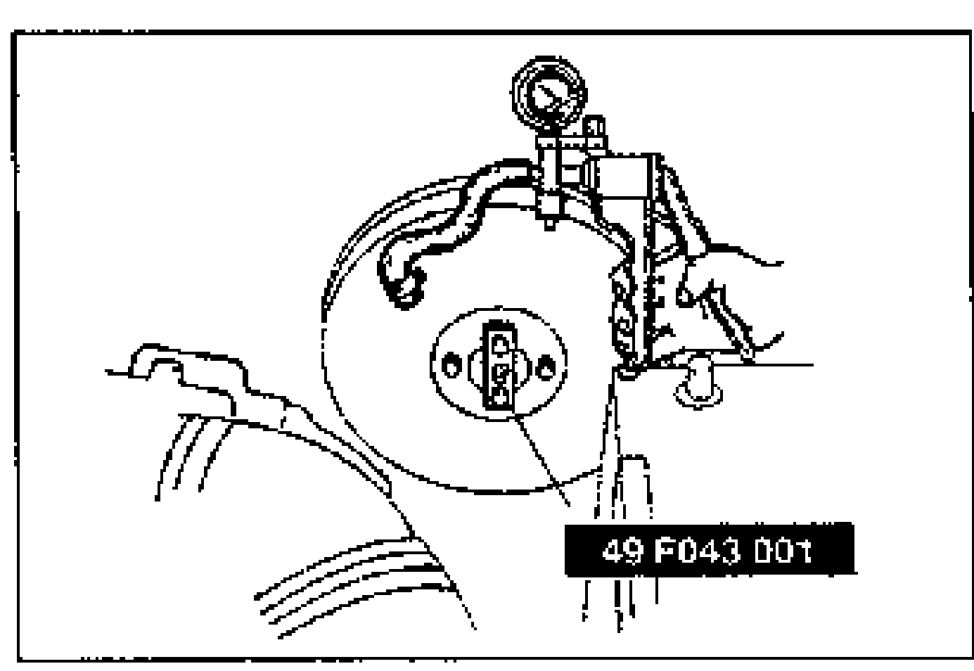 49 F043 001
 - 3Invert the adjustment gauge used in Step 1 and place it on the power brake unit.
- 4Measure the clearance between the end of the gauge and the push rod of the power brake unit. If it is not 0 mm {0 in}, loosen the push rod locknut and turn the push rod to make the adjustment.
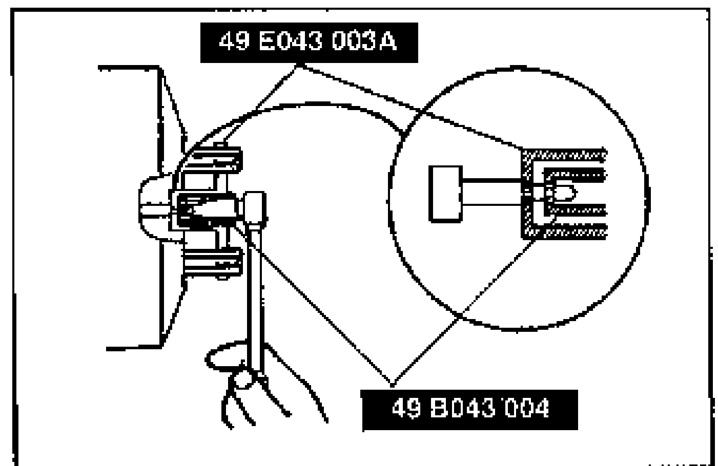 49 B043 004
NOTE
This adjustment produces the following distance.
Push rod-to-piston clearance
When vacuum applied to unit is approx. 66.7 kPa {500 mmHg, 19.7 inHg}
Push rod-to-piston clearance0.1–0.4 mm {0.004–0.015 in}
Brake pipe
Tighten the brake pipe flare nut with the SST.
| Specification | Value |
|---|---|
| Brake pipe flare nut | 12.8 - 21.5N·m |
Brake pipe flare nut
12.8 - 21.5N·m
Inspection
Fluid level sensor
Fluid level sensor inspection
- 1Disconnect the sensor connector.
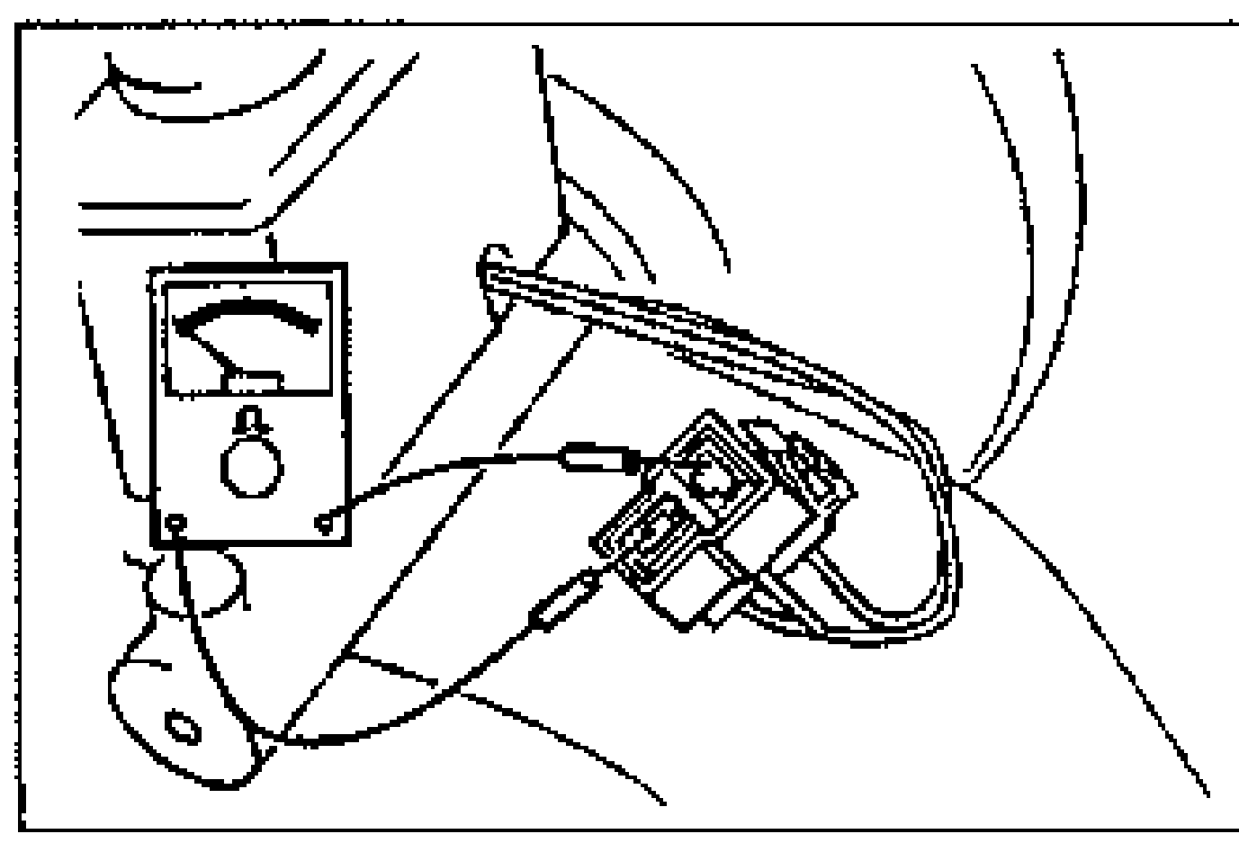
- 2Connect an ohmmeter to the connector.
- 3Starting with the fluid level above the MIN mark on the reservoir, verify that there is no continuity.
- 4Remove the brake fluid and verify continuity when the level is below the MIN mark.
- 5Replace the sensor if necessary.