
CONVENTIONAL BRAKE SYSTEM
P-20prose procedureRemoval Note
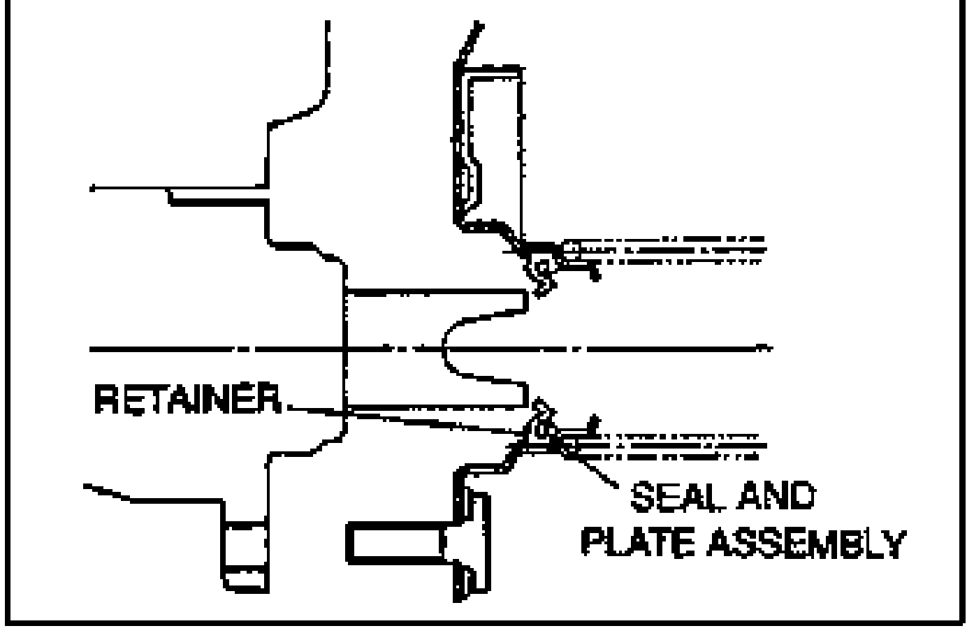
Retainer, seal and plate assembly
- 1Remove the retainer as shown in the figure.
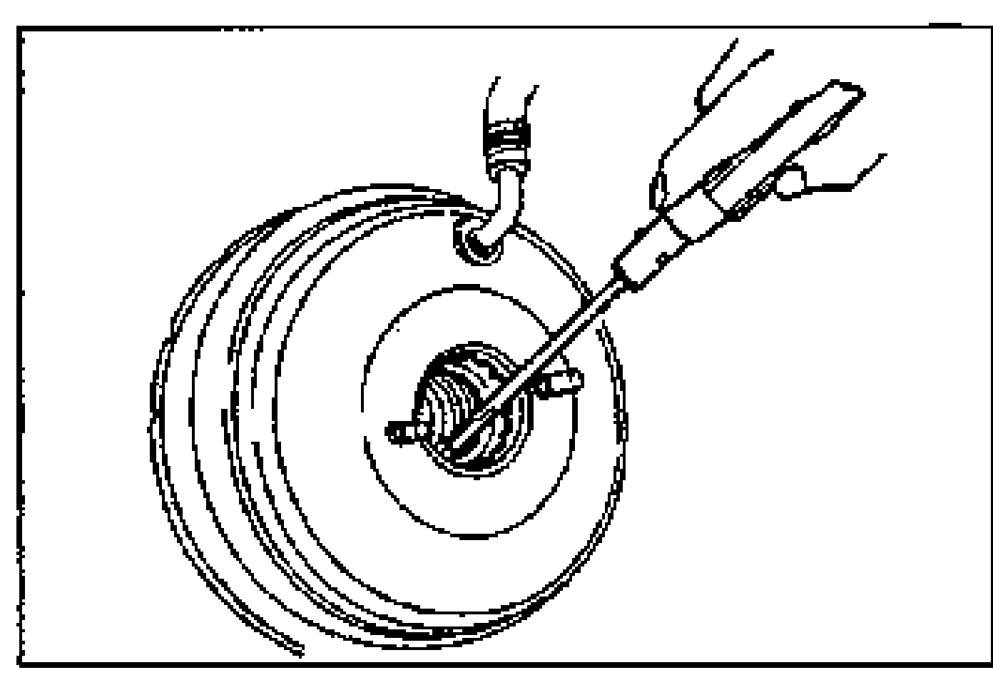
- 2Remove the seal and plate assembly.
Installation Note
Master cylinder, retainer, seal and plate assembly
- 1Remove the seal and plate assembly, and install the power brake unit gasket.
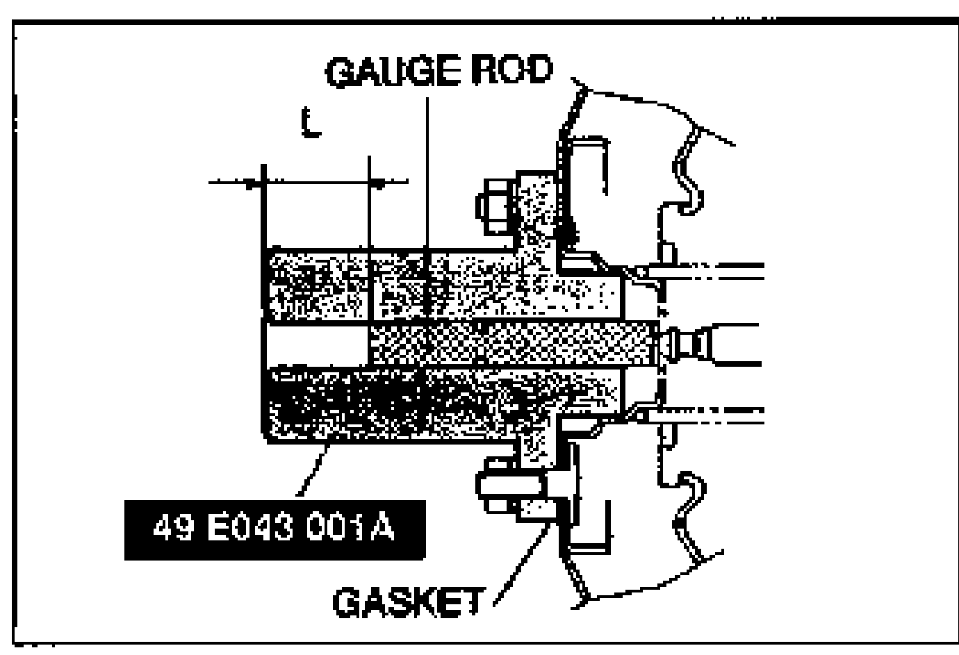 49 E043 001A
 - 2Adjust the push rod clearance as follows. (1) Attach the SST to the power brake unit as shown in the figure, and tighten the locknuts to the specified torque (Tightening torque: 9.9–15.6 N·m {100–160 kgf·cm, 86.8–138 in·lbf}). (2) Apply 66.7 kPa {500 mmHg, 19.7 inHg} vacuum by using a vacuum pump. (3) Measure the depth L of the gauge rod (Depth: 35.3–35.5 mm {1.390–1.397 in}). (4) If it is not specified, use the SSTs to adjust the push rod to the proper length. (5) Verify depth L of the gauge rod.Tightening torque: 9.9–15.6 N·m {100–160 kgf·cm, 86.8–138 in·lbf}Depth: 35.3–35.5 mm {1.390–1.397 in}
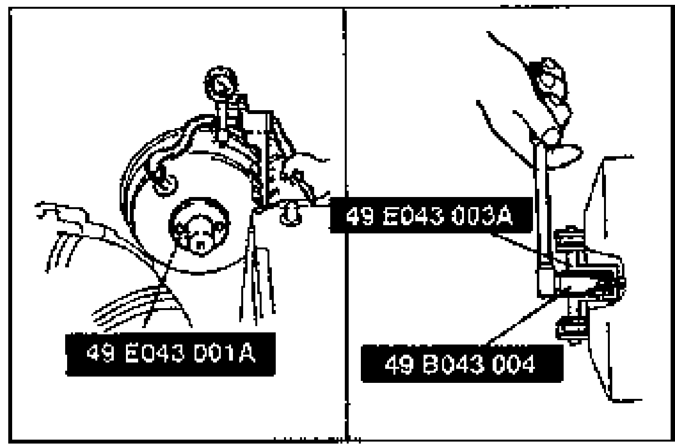 49 E043 001A
 - 3(1) Install the new retainer and the seal and plate assembly by using the SST. (2) Apply specified grease supplied in the repair kit to the seal plate assembly.
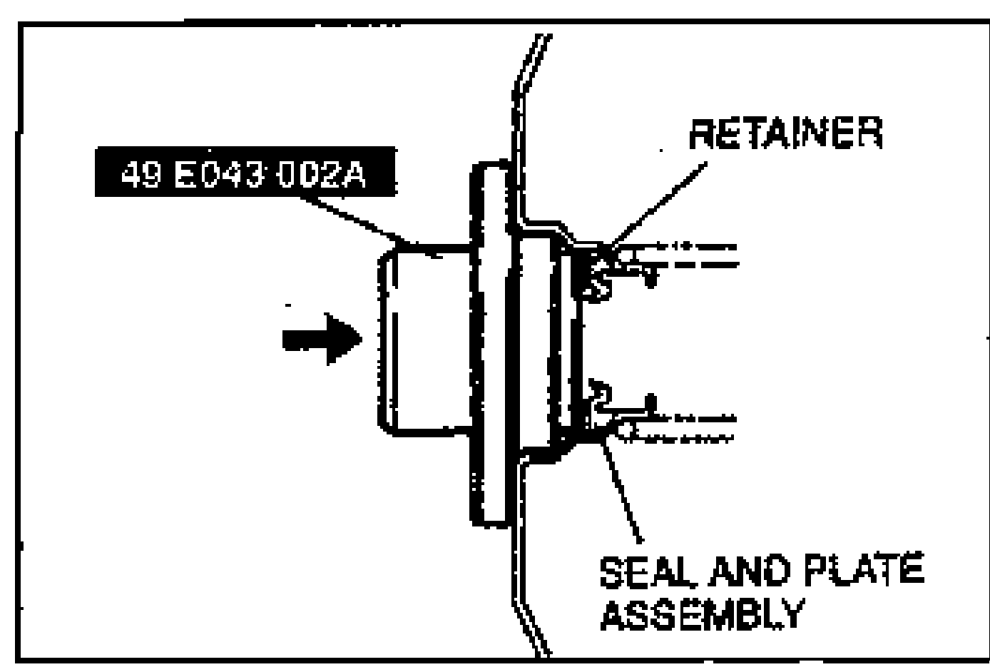 49 E043 002A
 - 4When installing the master cylinder into the power brake unit, be sure to align it correctly, fitting the master cylinder squarely into the power brake unit seal. Do not roll the lip of the power brake unit seal.
| Specification | Value |
|---|---|
| SST locknuts | 9.9 - 15.6N·m |
| DepthGauge rod depth L with vacuum applied | 35.3–35.5 mm {1.390–1.397 in} |
SST locknuts
9.9 - 15.6N·m
DepthGauge rod depth L with vacuum applied
35.3–35.5 mm {1.390–1.397 in}