
IDLE AIR CONTROL SYSTEM
F2-99prose procedureNeutral (MTX) or P (ATX) for idle-speed check.
System Operation
- 1Warm up the engine to normal operating temperature.
- 2Shift the selector lever to neutral (MTX) or P (ATX).
- 3Turn all electric loads OFF.
- 4Connect a tachometer to the data link connector terminal IG- as shown.
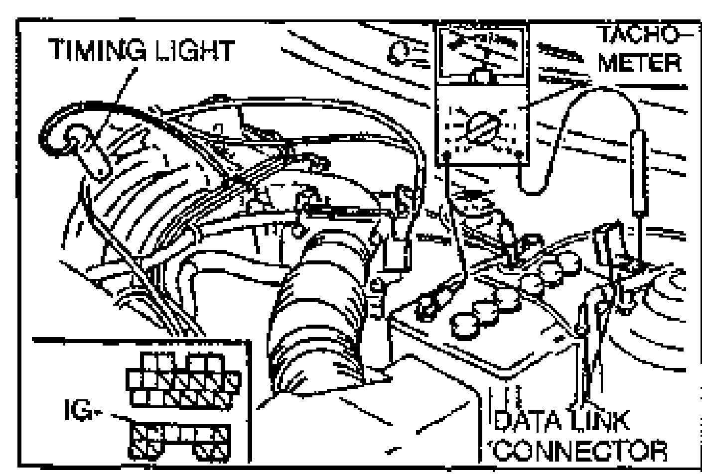
- 5Verify that the coolant fan is turned off.
- 6Verify that the idle speed is within the specification.Idle speed (Neutral or P range): 640-700 rpm {670 ± 30 rpm}
- 7If not within the specification, adjust the idle speed. (Refer to page F2-71.)
- 8Verify that the idle speed is within the specification under the conditions below.
- 9If not as specified, check the related wiring harness, switches and sensors.
| Specification | Value |
|---|---|
| Idle speed (Neutral or P range) | 640-700rpm {670 ± 30 rpm} |
Idle speed (Neutral or P range)
640-700rpm {670 ± 30 rpm}
Idle speed under conditions
No load
Idle speed {rpm}640-700
Electrical load ON
Idle speed {rpm}640-700
Air Conditioner ON
Idle speed {rpm}720-780
P/S operating
Idle speed {rpm}640-700
BAC VALVE
Inspection
Air valve
Air valve inspection
- 1Connect the data link connector terminals TEN and GND with a jumper wire.
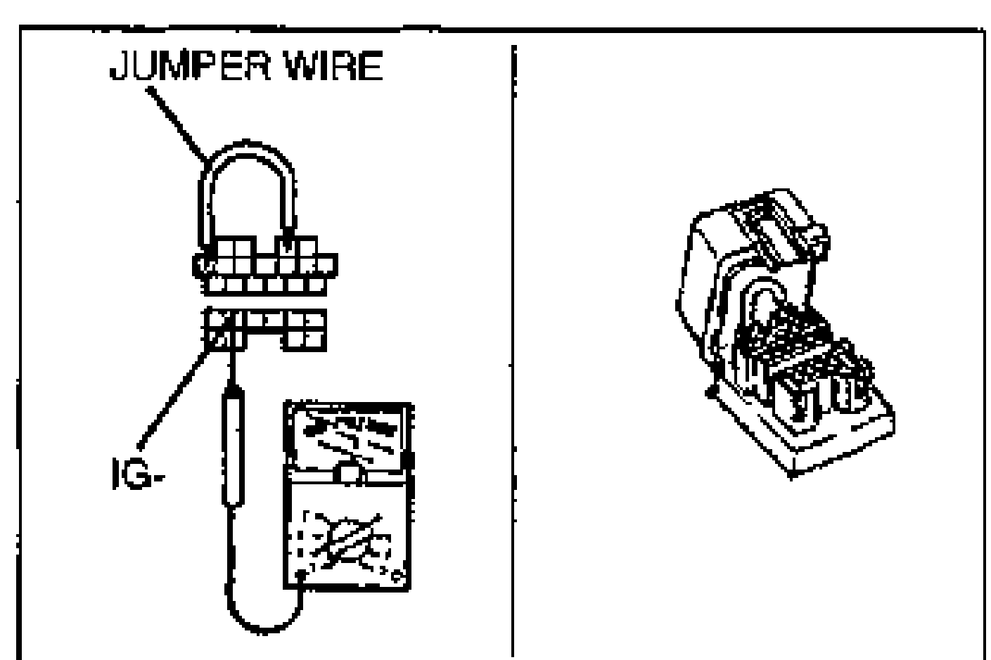
- 2Connect a tachometer to the data link connector terminal IG-.
- 3Start the engine.
- 4The idle speed should decrease gradually as the engine warms up.
Idle air control valve
Idle air control valve inspection
- 1Disconnect the idle air control valve connector.
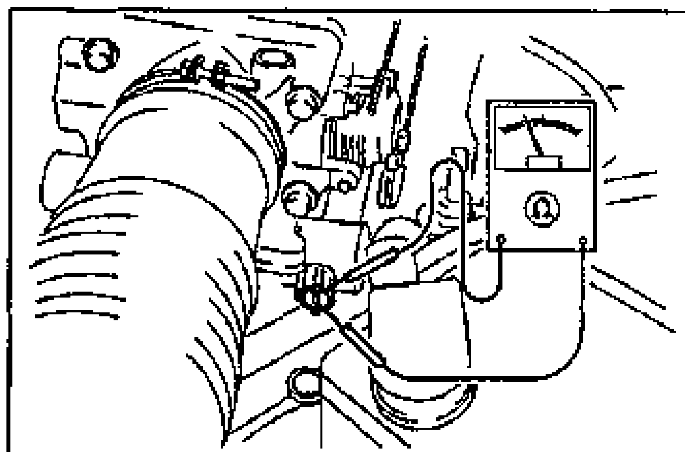
- 2Measure the resistance of the idle air control valve with an ohmmeter.Resistance: 10.7-12.3 Ω (at 20°C {68°F})
- 3If not as specified, replace the idle air control valve.
| Specification | Value |
|---|---|
| Idle air control valve resistanceat 20°C {68°F} | 10.7-12.3Ω |
Idle air control valve resistanceat 20°C {68°F}
10.7-12.3Ω
Removal / Installation
(Refer to page F2-95.)