
FUEL INJECTOR - Inspection
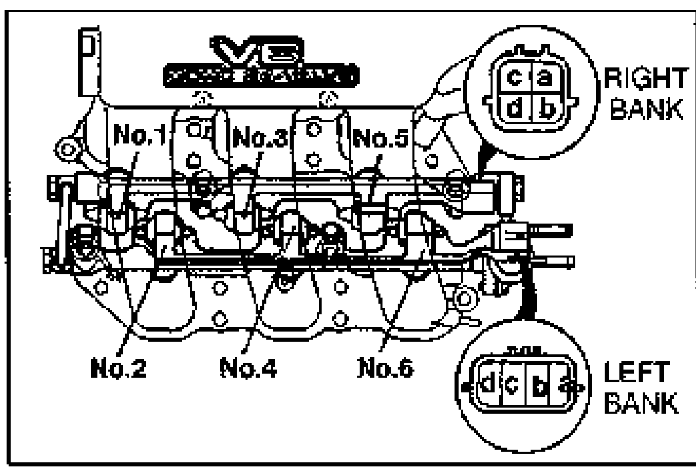
F2-117prose procedureInjector resistance terminal mapping is for the V6 (K8-ZE) with right and left banks.
Inspection
NOTE
It is not necessary to remove the fuel injectors to perform the following procedures.
Fuel injector resistance
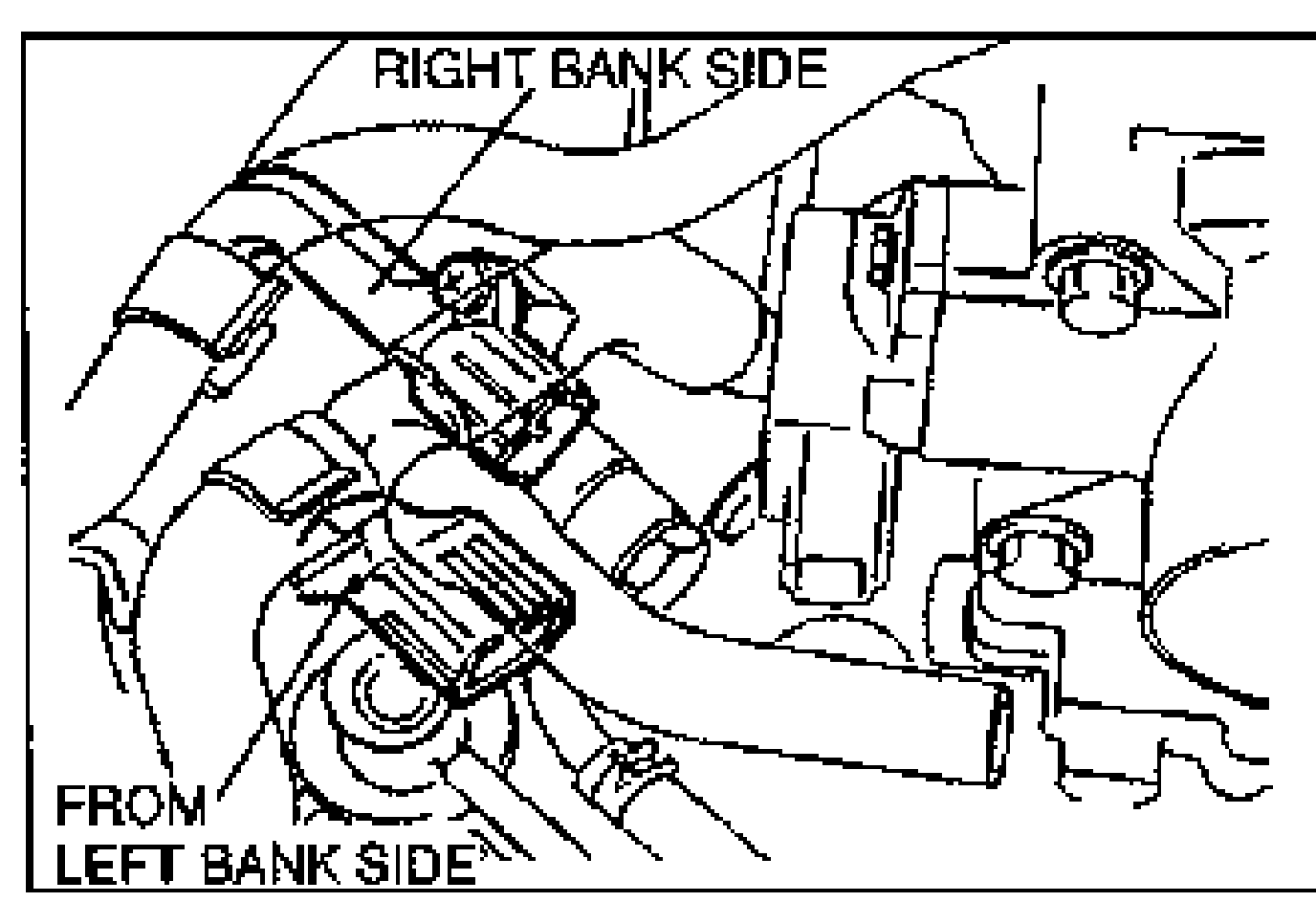
- 1Disconnect the fuel injector connectors as shown in the figure.
- 2Measure the resistance of the fuel injector with an ohmmeter.
- 3If not as specified, check the connectors for continuity and poor connection.
- 4If the harness is OK, replace the fuel injector.
Fuel injector harness terminal / injector number
Right bank
Terminala-b
Injector No.1
Right bank
Terminala-c
Injector No.5
Right bank
Terminala-d
Injector No.3
Left bank
Terminald-c
Injector No.2
Left bank
Terminald-b
Injector No.4
Left bank
Terminald-a
Injector No.6
| Specification | Value |
|---|---|
| Resistance20°C {68°F} | 12-16 ohmohm |
Resistance20°C {68°F}
12-16 ohmohm
Fuel leakage test
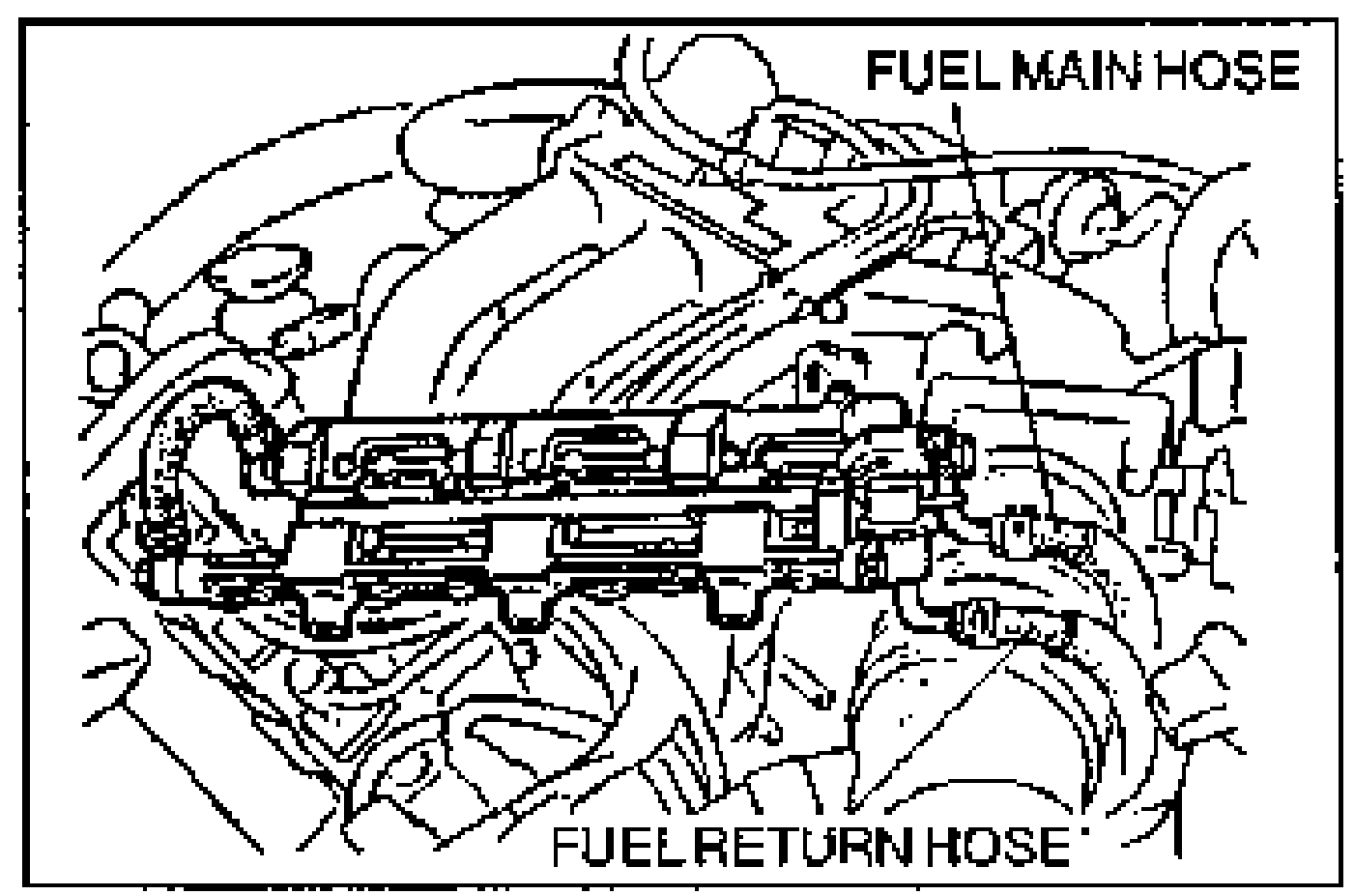
- 1Remove the fuel injector together with fuel distributor from intake manifold as shown in figure.
- 2Connect the fuel hose and fuel return hose.
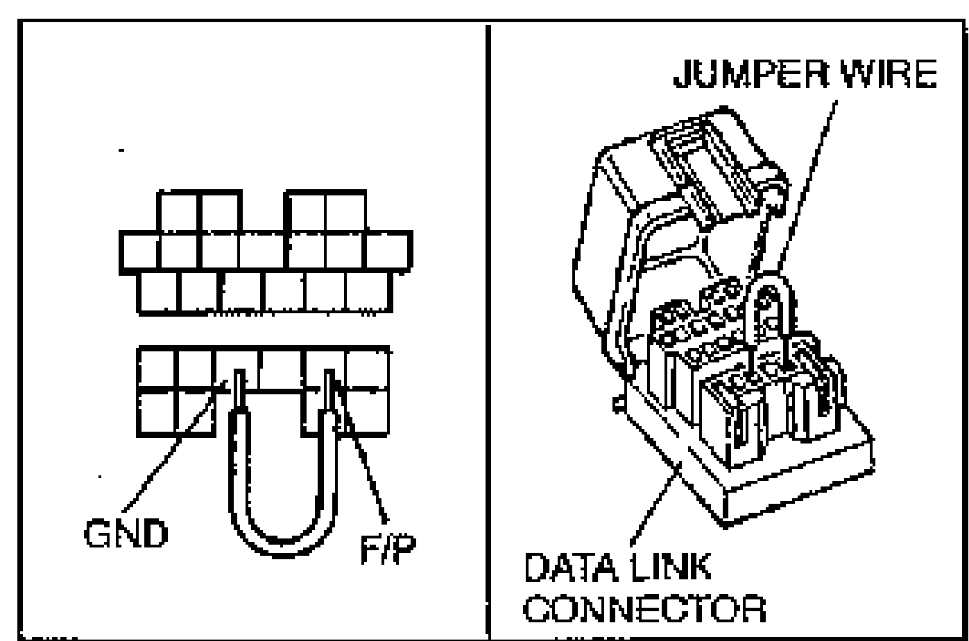
- 3Connect the data link connector terminals F/P and GND by using a jumper wire.
- 4Turn the ignition switch to ON and check for fuel leaks from the fuel injector.
- 5If not as specified, check the fuel injector O-ring and fuel distributor contact face.
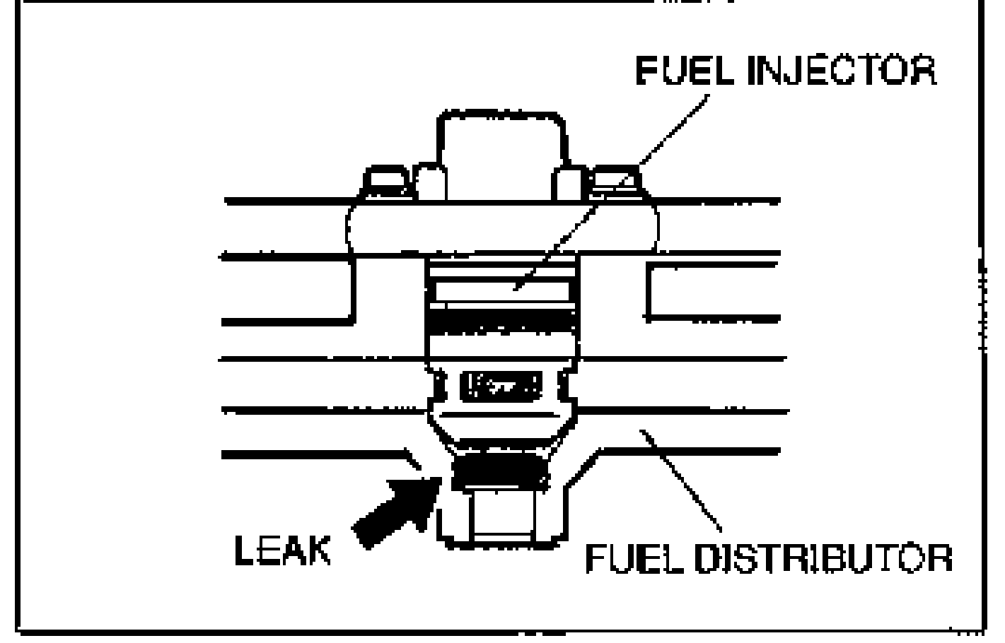
- 6Install the fuel injector.
- 7Turn the ignition switch to ON and check for fuel leaks from the fuel injector.
- 8If not as specified, replace the fuel injector.
| Specification | Value |
|---|---|
| Fuel leakage | Less than 1 drop/2 min. |
Fuel leakage
Less than 1 drop/2 min.