
CONTROL SYSTEM — Volume Air Flow Sensor / Throttle Position Sensor Inspection
F2-150prose procedureVOLUME AIR FLOW SENSOR
Inspection
- 1Check the volume air flow sensor body for cracks or damage.
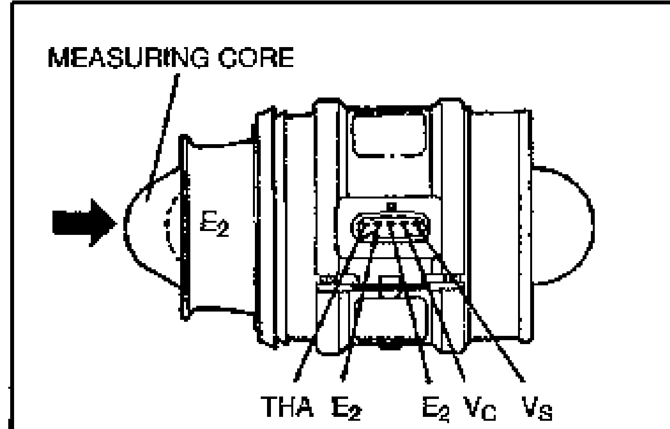
- 2Verify that the measuring core opens smoothly.
- 3Measure the resistance of the sensor by using a circuit tester.
Volume air flow sensor resistance
E2 ↔ VS
Resistance (Ω)200—1,000 (Closed; 20°C {68°F}); 20—800 (Open; 20°C {68°F})
E2 ↔ VC
Resistance (Ω)200—400 (Closed ↔ Open; 20°C {68°F})
E2 ↔ THA (Intake air temperature sensor)
Resistance (Ω)20°C {68°F}: 2,000—3,000; 60°C {140°F}: 400—700
Removal / Installation
(Refer to page F2-95.)
THROTTLE POSITION SENSOR
Inspection — Idle switch
- 1Turn the ignition switch to OFF and the throttle valve to the closed throttle position.
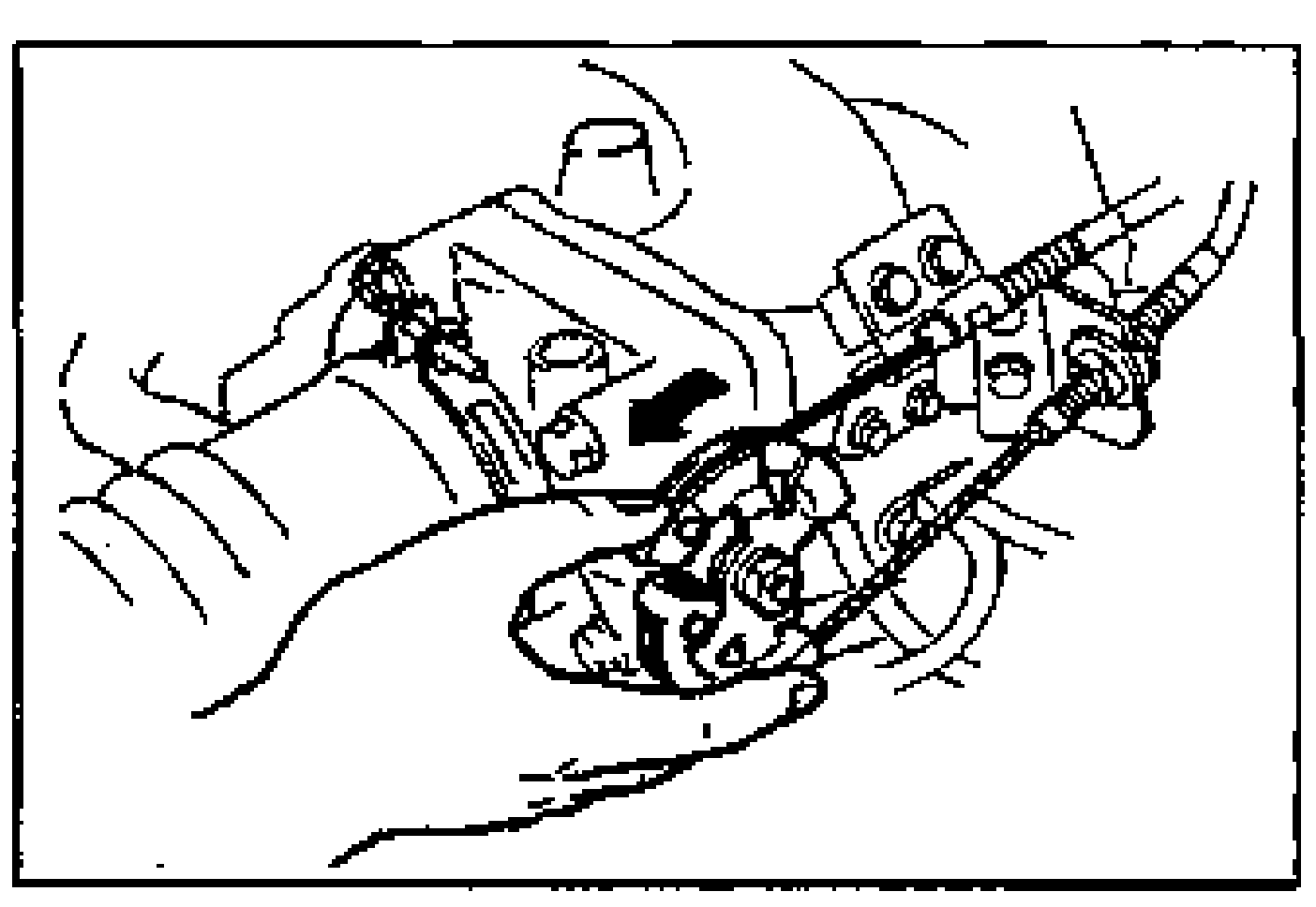
- 2Disconnect the throttle position sensor connector.
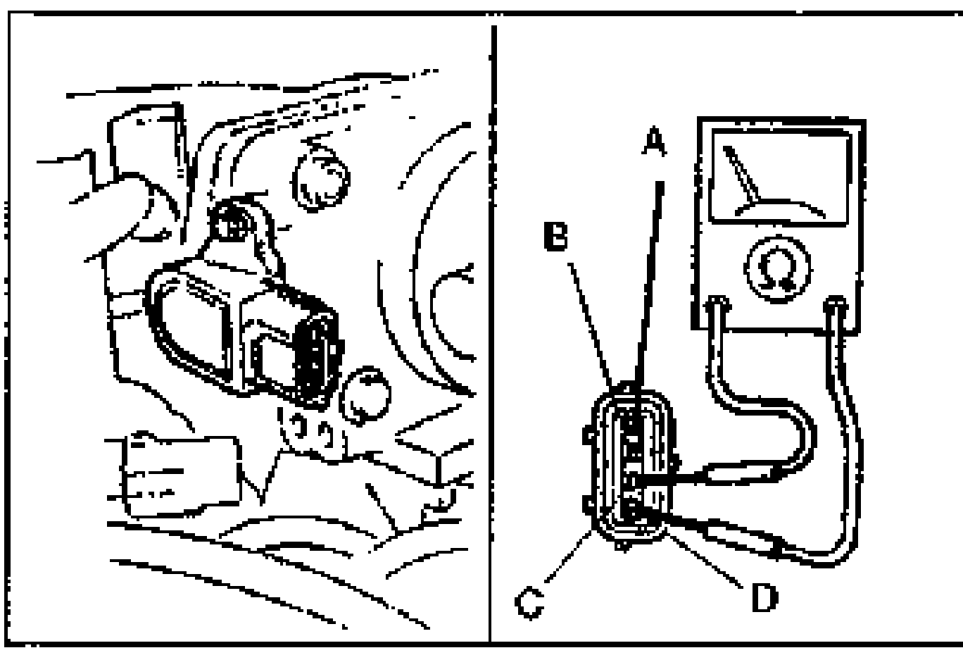
- 3Check continuity between the throttle position sensor terminals C and D.
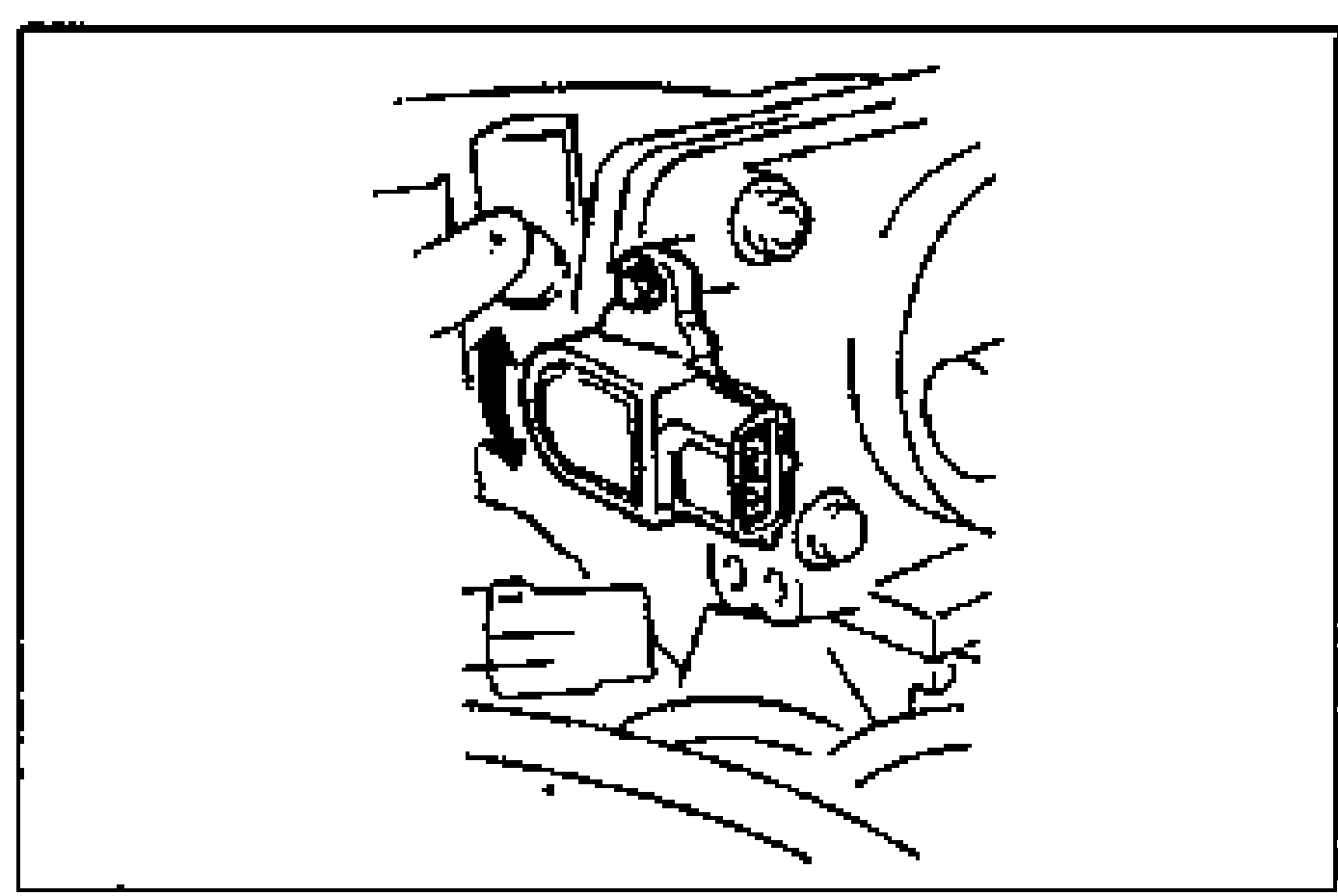
- 4If no continuity, adjust the throttle position sensor. (Refer to page F2-151.)
- 5Insert a feeler gauge of 0.5 mm {0.020 in} between the stopper and the throttle lever.
- 6Verify that there is no continuity between the throttle position sensor terminals C and D.
- 7If continuity, adjust the throttle position sensor. (Refer to page F2-151.)
Idle switch specification
C—D
Throttle valve closed throttle positionContinuity
Variable resister
- 1Remove the ECM. (Refer to page F2-141.)
- 2Connect the SSTs (Engine Signal Monitor and Adapter Harness) to the ECM.
- 3Set the SST (Engine Signal Monitor) to position 2F.
- 4Turn the ignition switch to ON.
- 5Rotate the throttle link by hand and verify that voltage is within the specification.
- 6If not as specified, adjust the throttle position sensor. (Refer to page F2-151.)
Variable resister specification
2F
Throttle valve position — Closed throttle position0.1—1.1V
Throttle valve position — Wide open throttle2.8—4.5V